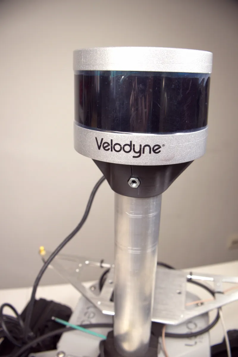
Velodyne Puck (VLP-16)
This tutorial will guide you through the process of connecting and using Velodyne Puck LiDAR sensor on your rover.
Light Detection and Ranging devices, or Lidars for short, are mechanisms used for mapping the environment, object detection, tracking the speed of vehicles and in a wide range of other applications. The VLP-16 has a range of 100 m, and the sensor's low power consumption (~8 W), light weight (830 g), compact footprint (~Ø103 mm x 72 mm), and dual return capability make it ideal not only for autonomous vehicles but also robotics and mobile terrestrial 3D mapping applications.
What to expect?
After finishing the tutorial you will have configured the Velodyne Puck LiDAR to work on your rover. You will be able to gather and visualize the data from the sensor.
Prerequisites
Mechanical integration
It's common for 3D lidars to be attached some distance above the mounting plate of a robot. This procedure allows you to avoid the need to filter data related to the reflection of the laser beam from the robot's elements.
The easiest solution for attaching the Velodyne Puck above the mounting plate of a Leo Rover would be using our Universal Camera Mast.
Referenced products
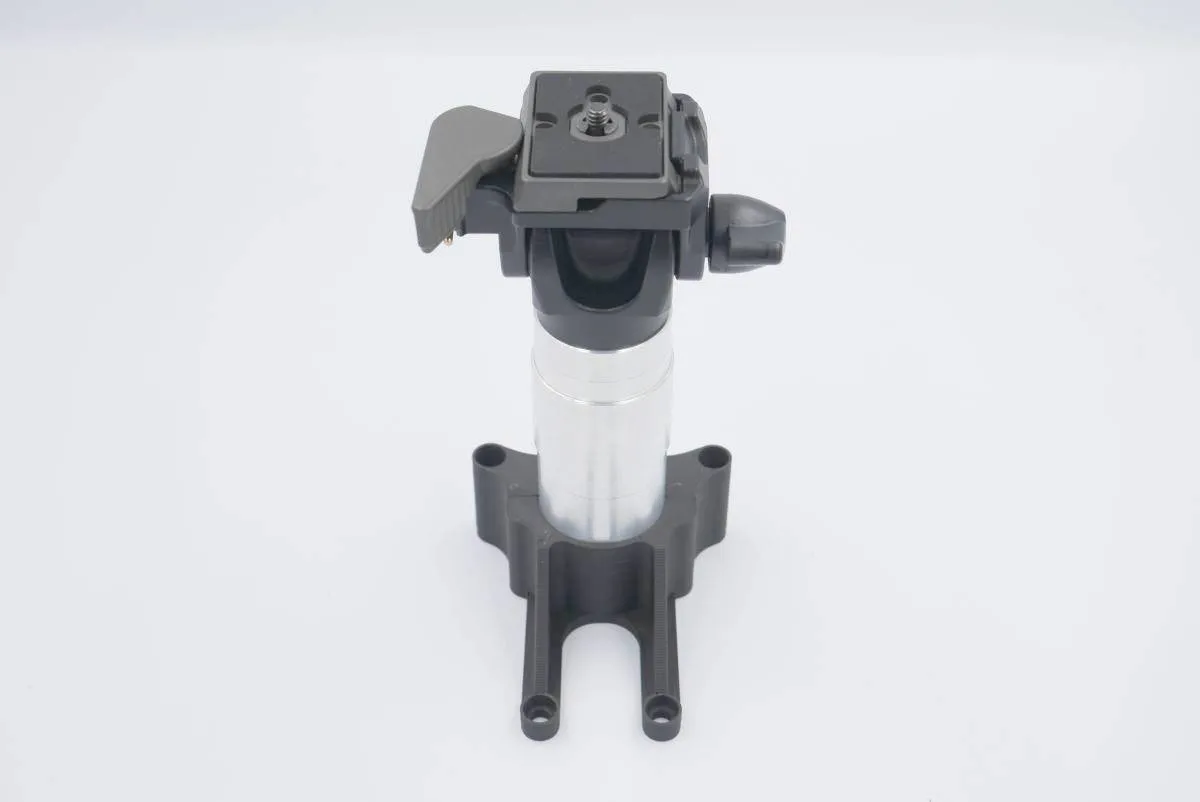
However, you can also design a custom eg. like the one shown in the picture below.
Wiring and electronics connection
Whatever your mounting solution might be, You'll still have to connect the lidar to the rover somehow.
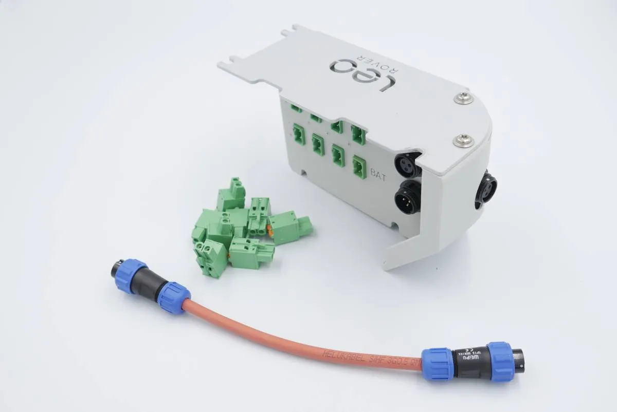
The USB port placed on the mounting plate of the rover is not going to be enough. In order for the Lidar to work You'll have to provide an ethernet connection between it, and the rover.
Kacper from our team likes to remove the micro-usb port entirely and run the wire straight through the newly created hole. This solution, combined with the use of a cable gland, keeps the MEB box waterproof.
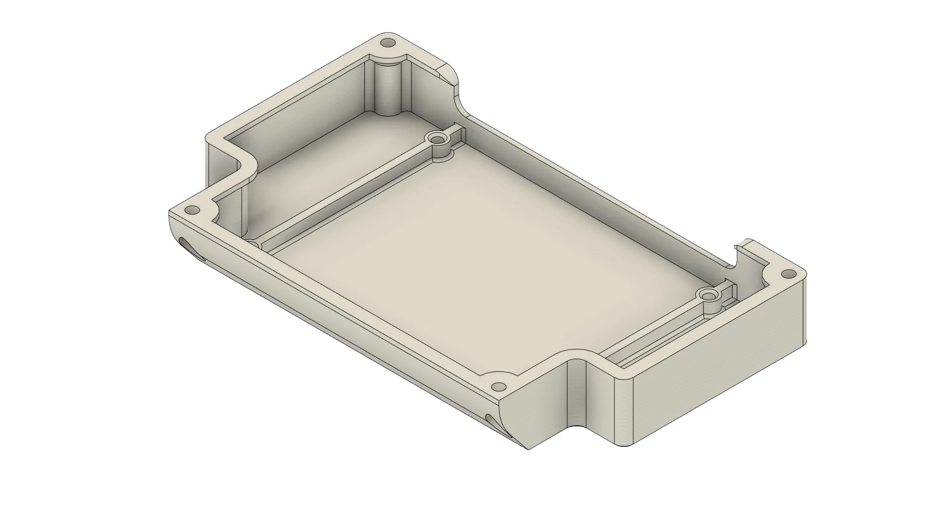
Second common solution involves printing a new cover for the MEB box. Dev cover found here, provides a wide opening for running wires straight into the MEB. This solution can be extremely useful in projects that don't need to be waterproof.
If the camera isn't the only thing connected to the rover you might need to provide an external power connection. Powerbox might come in handy in such situations.
Software integration
Configuring the sensor for the rover
In this section Velodyne Puck will be connected to a PC in order to modify its configuration for the rover. These instructions will contain setup on a PC with Ubuntu. If you are looking to connect to the sensor on Windows you can checkout VLP-16 User Manual (chapters 4.1.2 and 4.2.2).
If in this part you encounter problems you can try turning off your WiFi.
Power the LiDAR via the included adapter and connect the sensor to an ethernet port on your computer.
Go to the Network tab in settings and enter Wired settings.
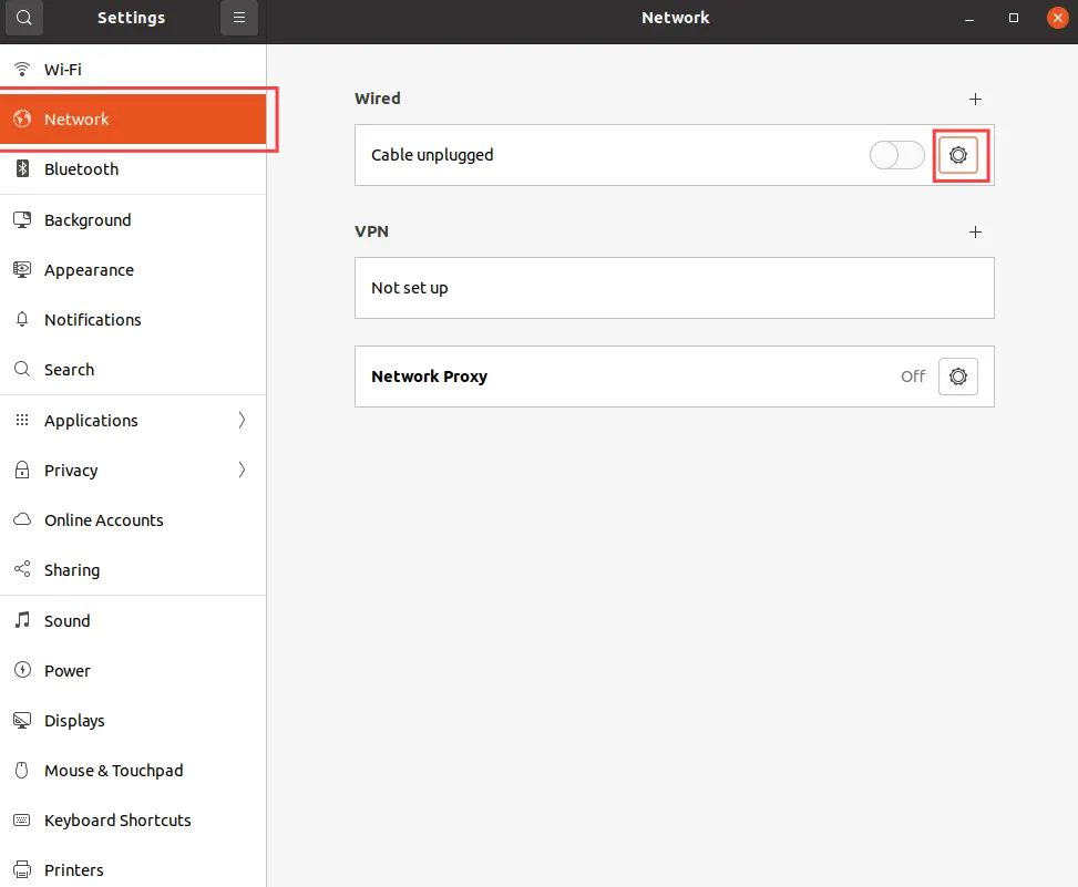
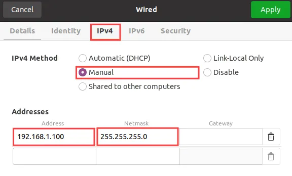
In the wired settings go to IPv4 tab, choose manual IPv4 method, type in the IP
for your computer (in this tutorial this IP will be 192.168.1.100 however you
can choose any IP in that network that is not sensor's IP), add a
255.255.255.0 Netmask and then click Apply.
Open the terminal and add a static route do the sensor's IP address - by default
it should be 192.168.1.201. Replace eth0 with your ethernet interface
signature - you can find this using ifconfig command.
sudo route add 192.168.1.201 eth0
Now you should be able to connect to the sensor. You can check the connection by pinging the LiDAR.
ping 192.168.1.201
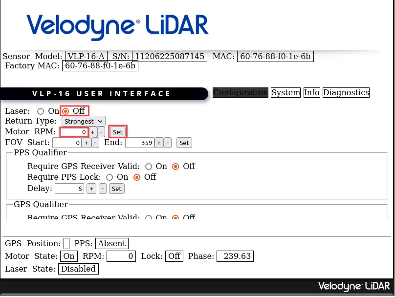
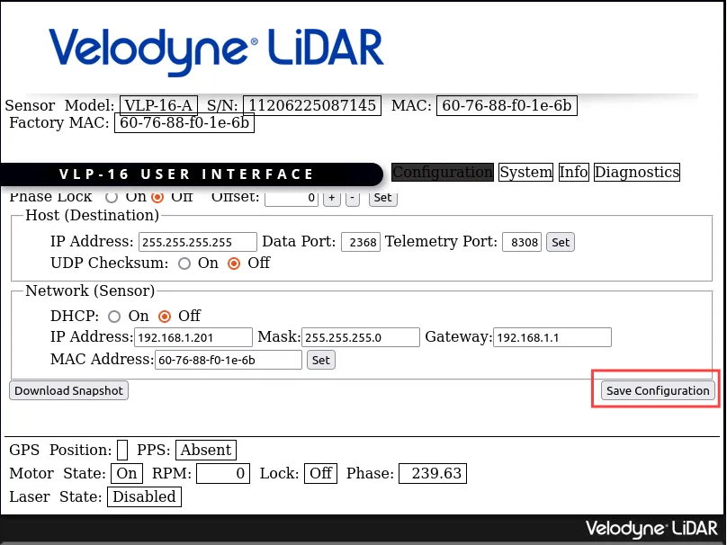
Open your browser and type in the sensor's IP address (192.168.1.201). The
following page should appear:
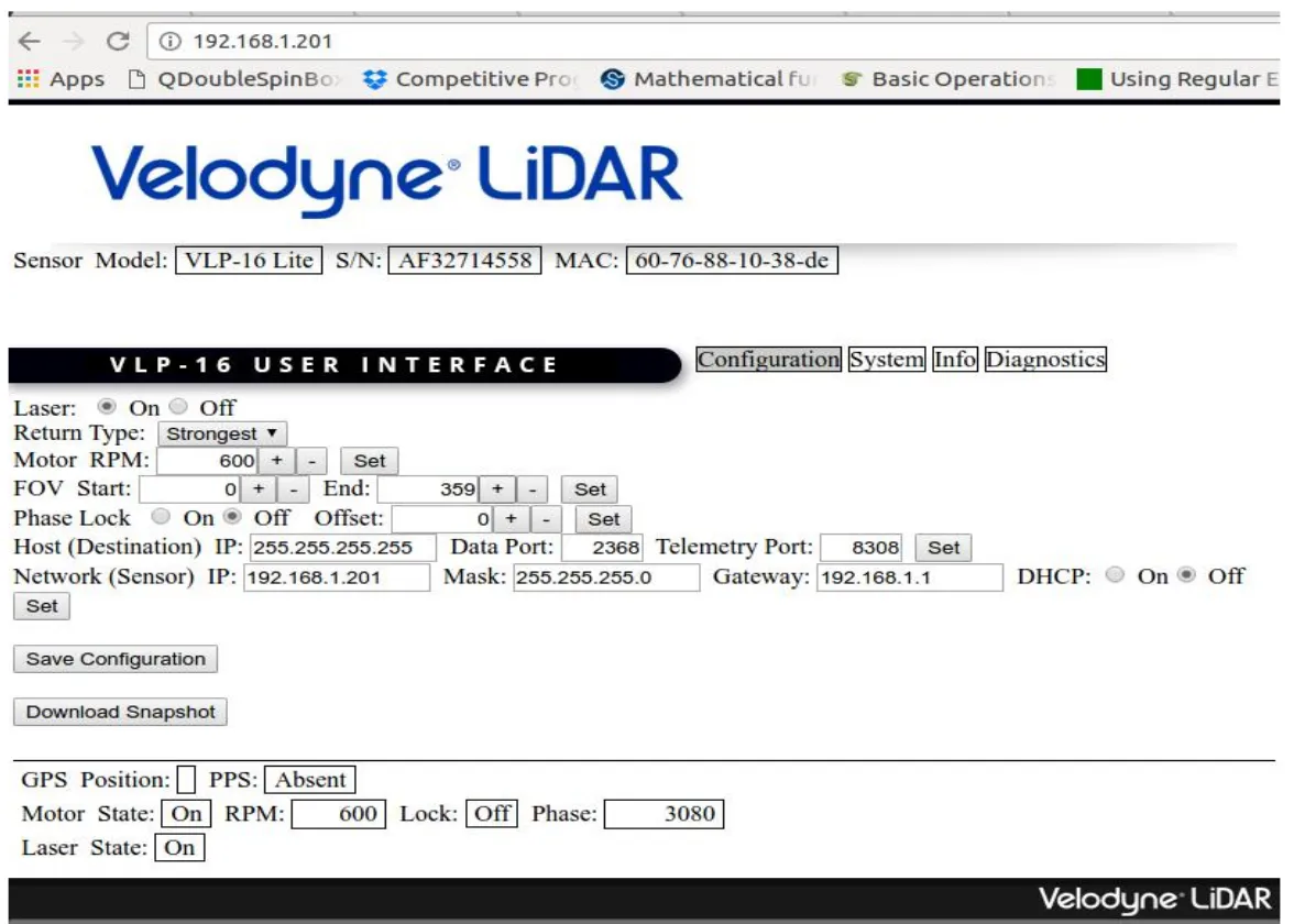
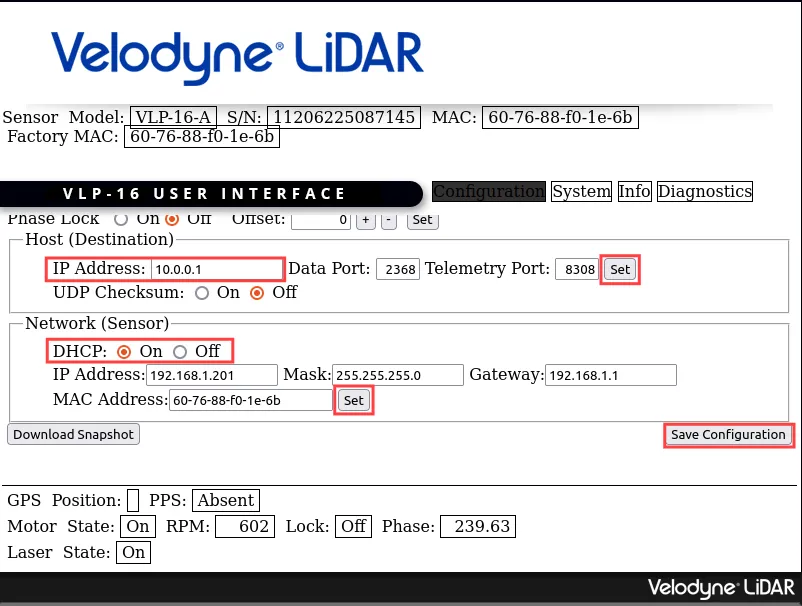
In these settings scroll down and in Host (Destination) section change IP
Address to 10.0.0.1 and click Set. In Network (Sensor) section change
DHCP to On and click Set. Finally click Save Configuration button.
For a better understanding of what each option does you can use VLP-16 User Manual.
You can now disconnect and power down the sensor. After it's next booted up these changes will persist.
Setting up the Velodyne sensor on the rover
Power the LiDAR via the adapter and connect in to the ethernet port on the rover's Raspberry Pi.
Now the sensor will get an IP assigned by rover's DHCP server. You can check
this IP by installing and using nmap.
sudo apt install nmap
nmap 10.0.0.1/24
In output there will also be the address of Raspberry Pi and other devices
connected to the rover such as your computer, however other connections should
have distinctive names, such as leo (10.0.0.1).
To make sure that the sensor is connected you can type its IP address (the one
from nmap result) into the browser and you should see the VLP-16 User
Interface - the same as in the previous configuration.
From now on remember to use this new IP if sensor's IP is needed in any of the other modules.
ROS software installation
Make sure that system date is correct by writing this command in the terminal.
date
If the date is not correct you can set it to current date. Replace
YYYY-MM-DD HH:MM:SS with current date and time e.g. 2023-01-31 09:00:00.
sudo date -s 'YYYY-MM-DD HH:MM:SS'
Next make sure that all your packages are up to date.
sudo apt update && sudo apt upgrade
Now you can install Velodyne ROS package. Replace ROSDISTRO with your ROS
version e.g. noetic.
sudo apt install ros-ROSDISTRO-velodyne
If you haven't already, setup a ROS workspace.
mkdir -p ~/ros_ws/src
cd ~/ros_ws
catkin init
Go to the src directory in your workspace and clone a repository with Velodyne Driver.
cd ~/ros_ws/src
git clone https://github.com/ros-drivers/velodyne.git
Go back to main workspace directory and install ROS dependencies. Replace ROSDISTRO with your ROS version e.g. noetic.
cd ~/ros_ws
sudo rosdep init
rosdep update
rosdep install --from-paths src --ignore-src --rosdistro ROSDISTRO -y
You can now build your workspace.
catkin build --make-args -j2
Adding Velodyne puck to URDF
Your robot should be aware of where the scanner is located and what space it
occupies. You can ensure it does that by creating an URDF model file of the
sensor in /etc/ros/urdf directory.
<?xml version="1.0"?>
<robot>
    <link name="velodyne_base_link">
      <visual>
        <origin rpy="0 0 0" xyz="0 0 0.03585"/>
        <geometry>
          <cylinder radius="0.0516" length="0.0717"/>
        </geometry>
      </visual>
      <collision>
        <origin rpy="0 0 0" xyz="0 0 0.03585"/>
        <geometry>
          <cylinder radius="0.0516" length="0.0717"/>
        </geometry>
      </collision>
    </link>

    <link name="velodyne">
      <inertial>
        <mass value="0.1"/>
        <origin xyz="0 0 0"/>
        <inertia ixx="0.1" ixy="0" ixz="0" iyy="0.1" iyz="0" izz="0.1"/>
      </inertial>
    </link>

    <joint name="velodyne_base_mount_joint" type="fixed">
      <origin xyz="0.0775 0 0"/> <!-- TODO after sensor is mounted -->
      <parent link="base_link"/>
      <child link="velodyne_base_link"/>
    </joint>

    <joint name="velodyne_base_scan_joint" type="fixed" >
      <origin xyz="0 0 0.0377" rpy="0 0 0" />
      <parent link="velodyne_base_link" />
      <child link="velodyne"/>
    </joint>
</robot>
And including it in the description file that is uploaded at boot.
<xacro:include filename="/etc/ros/urdf/laser.urdf.xacro"/>
You can experiment with the URDF file and create a more representative model of the sensor by adding more visual and collision tags or by including meshes in STL or COLLADA format.
The last step is to either reboot the robot or restart the leo service.
sudo systemctl restart leo
Running Velodyne Puck ROS node
To run the node type:
roslaunch velodyne_pointcloud VLP16_points.launch
Adding the node to autostart
Open /etc/ros/robot.launch and add this line inside <launch> tag:
<include file="$(find velodyne_pointcloud)/launch/VLP16_points.launch" />
Now you can reboot the robot or restart the leo service
sudo systemctl restart leo
Modifying Velodyne Puck configuration to be more power efficient (optional)
If you are not using the LiDAR at all times (its ROS node is not running at all times) you can use instructions below to prolong battery life. By default Velodyne Puck turns on its motor and laser on power up which consumes a lot of battery. However its configuration can be adjusted not to not turn on on power up and a ROS node can be added to turn the sensor on when needed.
To do that you need to reconfigure Velodyne Puck first.
Enter the configuration site in your web browser by typing sensor's IP.
In the settings turn laser off and set motor RPM to 0.
Next scroll down and click Save configuration. Now the motor and laser should not be running after power up.
Now you can go to your the velodyne_pointcloud directory where the scripts
will be added.
cd ~/ros_ws/src/velodyne/velodyne_pointcloud/scripts
In this directory create config_velodyne.sh and velodyne_config_manager.py
and copy the code below into them.
#!/bin/bash

# Check if the necessary command-line arguments are provided
if [ "$#" -ne 3 ]; then
    echo "Error: Incorrect number of arguments. Usage: $0 <target_ip> <rpm_count> <laser_status>"
    exit 1
fi

# Assign command-line arguments to variables
target_ip="$1"
rpm_count="$2"
laser_status="$3"

while true; do
    ping -c 1 $target_ip > /dev/null 2>&1

    # Check the exit status of the ping command
    if [ $? -eq 0 ]; then
        break
    else
        sleep 1
    fi
done

curl --data "rpm=$rpm_count" http://$target_ip/cgi/setting
sleep 1
curl --data "laser=$laser_status" http://$target_ip/cgi/setting
#!/usr/bin/env python

import rospy
import subprocess
from std_srvs.srv import Empty, EmptyResponse
import os

class VelodyneConfigManager:
    def __init__(self):
        self.target_ip = rospy.get_param("~target_ip", "192.168.1.201")

        script_filename = "config_velodyne.sh"
        script_dir = os.path.dirname(os.path.abspath(__file__))
        self.script_path = os.path.join(script_dir, script_filename)

    def change_velodyne_config(self, rpm_count, laser_status):
        # Check if the script exists
        if os.path.exists(self.script_path):
            rospy.loginfo("Changing velodyne config at target IP: %s, RPM count: %d, Laser status: %s",
                          self.target_ip, rpm_count, laser_status)

            # Run the Bash script with command-line arguments
            subprocess.run([self.script_path, self.target_ip, str(rpm_count), laser_status])
        else:
            rospy.logerr("Script not found at %s", self.script_path)

    def start_velodyne(self, req):
        self.change_velodyne_config(600, "on")
        return EmptyResponse()

    def stop_velodyne(self, req):
        self.change_velodyne_config(0, "off")
        return EmptyResponse()

if __name__ == "__main__":
    rospy.init_node("velodyne_config_manager_node", anonymous=True)
    manager = VelodyneConfigManager()

    # Start velodyne on startup
    manager.change_velodyne_config(600, "on")

    rospy.Service("velodyne_change_rpm_laser_on", Empty, manager.start_velodyne)
    rospy.Service("velodyne_change_rpm_laser_off", Empty, manager.stop_velodyne)

    rospy.spin()

    # Stop after node is shutdown
    manager.change_velodyne_config(0, "off")
Create a launch file for the node. Remember to change the value of target_ip
parameter to your Velodyne Puck IP.
<launch>
  <param name="target_ip" type="string" value="192.168.1.201" />

  <node name="velodyne_config_manager_node" pkg="leo_velodyne" type="velodyne_config_manager.py" output="screen" />

  <include file="$(find velodyne_pointcloud)/launch/VLP16_points.launch" />
</launch>
Now you can add the following lines to CMakeLists.txt of the
velodyne_pointcloud package:
install(PROGRAMS scripts/velodyne_config_manager.py
        DESTINATION ${CATKIN_PACKAGE_BIN_DESTINATION})
Build the workspace.
cd ~/ros_ws
catkin build --make-args -j2
To run the LiDAR you can now use:
roslaunch leo_velodyne leo_velodyne.launch
If the sensor is launched this way and connection to it can be established, ROS services to turn the LiDAR on or off are available.
rosservice call /velodyne_change_rpm_laser_on
rosservice call /velodyne_change_rpm_laser_off
Examples
The robot should publish the PointCloud2 messages on the /velodyne_points
topic. You can check the raw data that it sends by typing:
rostopic echo /velodyne_points
If you have ROS installed on your computer, you can get a more graphical representation of the data with RViz. If you don't have ROS, you can follow this guide:
Before starting RViz, make sure you completed the Connecting another computer to ROS network section of ROS Development tutorial:
Now, open RViz by typing rviz in the terminal, or, if you have the leo_viz
package installed, type:
roslaunch leo_viz rviz.launch
This will start RViz with visualization of the current robot model.
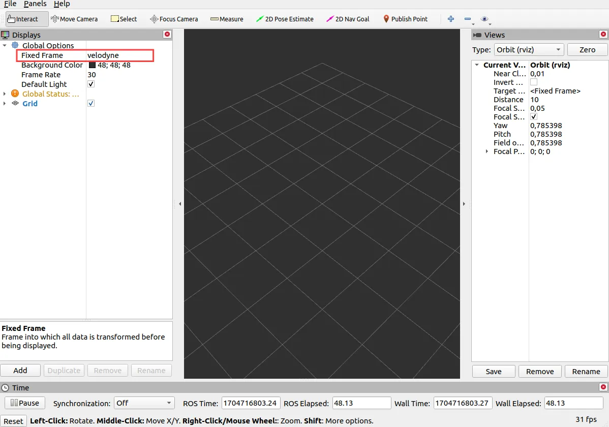
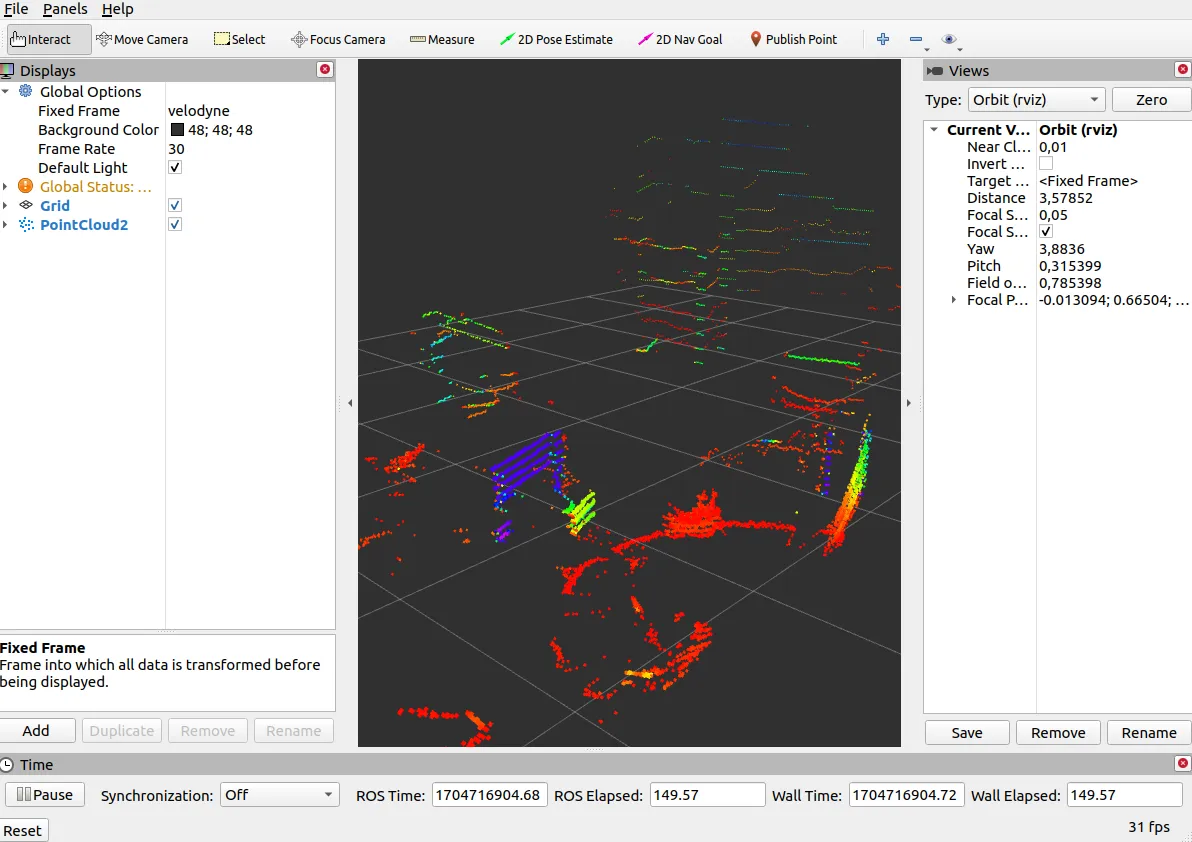
In Global Options change Fixed Frame to velodyne.
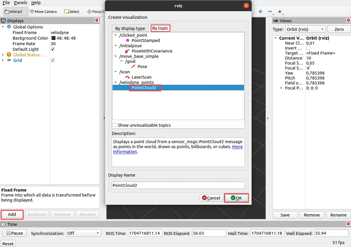
On the Displays panel click Add -> By topic and search for the
/velodyne_points topic. Choose the PointCloud2 display and click Ok.
Visualized pointcloud should look like this:
What next?
Lidars are commonly used in projects involving autonomous navigation, you might be interested in a tutorial about it.
They are however, not the only way of teaching a Leo Rover how to move on it's own. Check out our line follower tutorial if you want to learn more. You can also check our Integrations page for more instructions.