Leo Rover Specification
Introduction
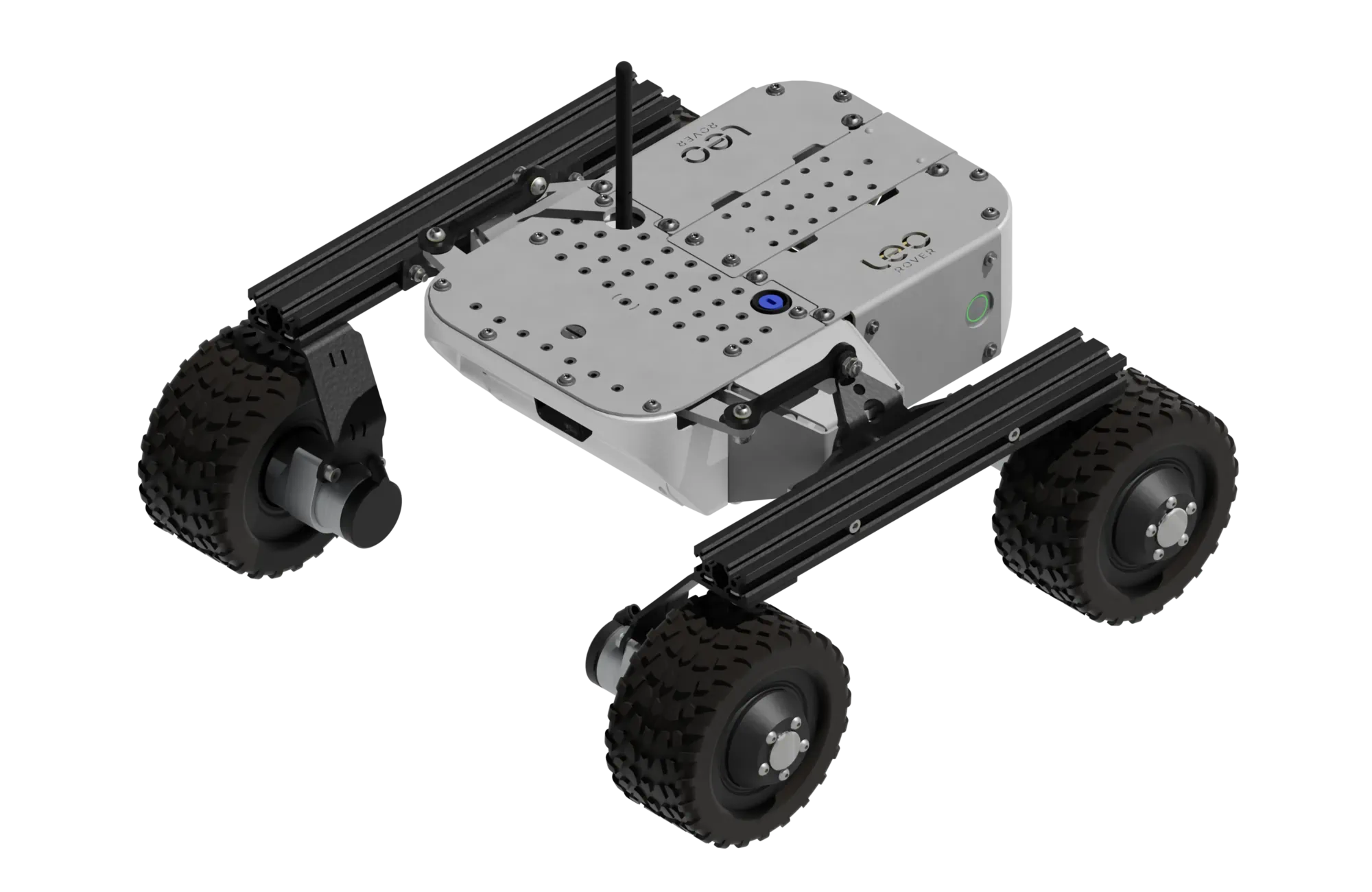
Leo Rover is a compact, 4-wheeled, remote-controlled robot designed for indoor and outdoor robotic project development, learning, and research applications. It is equipped with a built-in computer, a high-resolution camera, and a powerful battery, making it suitable for various tasks, including autonomous navigation, obstacle detection, and remote monitoring.
Main parameters
| Parameter | Value |
|---|---|
| Dimensions (LxWxH) | 424 mm x 445 mm x 303 mm |
| Weight | 7 kg |
| Maximum payload | 5 kg* |
| Maximum linear speed | 0.4 m/s |
| Maximum angular speed | 1 Rad/s |
| Estimated max. obstacle size | 70 mm |
| IP protection rating | IP 55 |
| Operating temperature | -10 °C to +40 °C |
| Run time | Up to 4 hours with standard battery |
| Connection range | Up to 100 m |
* - on standard tires
Traction parameters
| Parameter | Value |
|---|---|
| Track Width | 354 mm |
| Wheelbase length | 295 mm |
| Ground clearance | 108 mm |
| Climb grade (no payload) | 45° (100 %) |
| Climb grade with 5kg payload | 45° (100 %) |
| Hill grade traversal | 45° (100 %) |
| Nominal torque | 4 Nm |
| Maximum torque | 5.6 Nm |
Rover overview

Hardware specification
Dimensions

Components
| Name | Quantity | Description |
|---|---|---|
| Built-in computer | 1 | Raspberry Pi 5 - A single-board computer developed by Raspberry Pi Ltd. Key features:
|
| Wi-Fi adapter | 1 | Alfa AWUS036ACS: USB 2.0 Wi-Fi adapter (Realtek RTL8811AU). Dual-band 802.11ac (AC600: 150 Mbps 2.4GHz + 433 Mbps 5GHz). |
| Antenna | 1 | Dual-band (2.4 GHz / 5 GHz) placed on the top of the robot. |
| Front camera | 1 | Arducam 12.3MP 477M HQ Camera Module for Raspberry Pi with 158°(D) M12 Wide Angle Lens. |
| DC motors | 4 | Bühler Motors 1.61.077.414 connected to LeoCore. |
Block diagram
LeoCore controller
LeoCore is the main control board of the Leo Rover platform, responsible for power distribution, motor control, and communication with the onboard Raspberry Pi computer. Equipped with an STM32F401 microcontroller, it provides robust protection, precise motor drivers, and expandable I/O ports - making it a reliable foundation for robotics research, education, and prototyping.
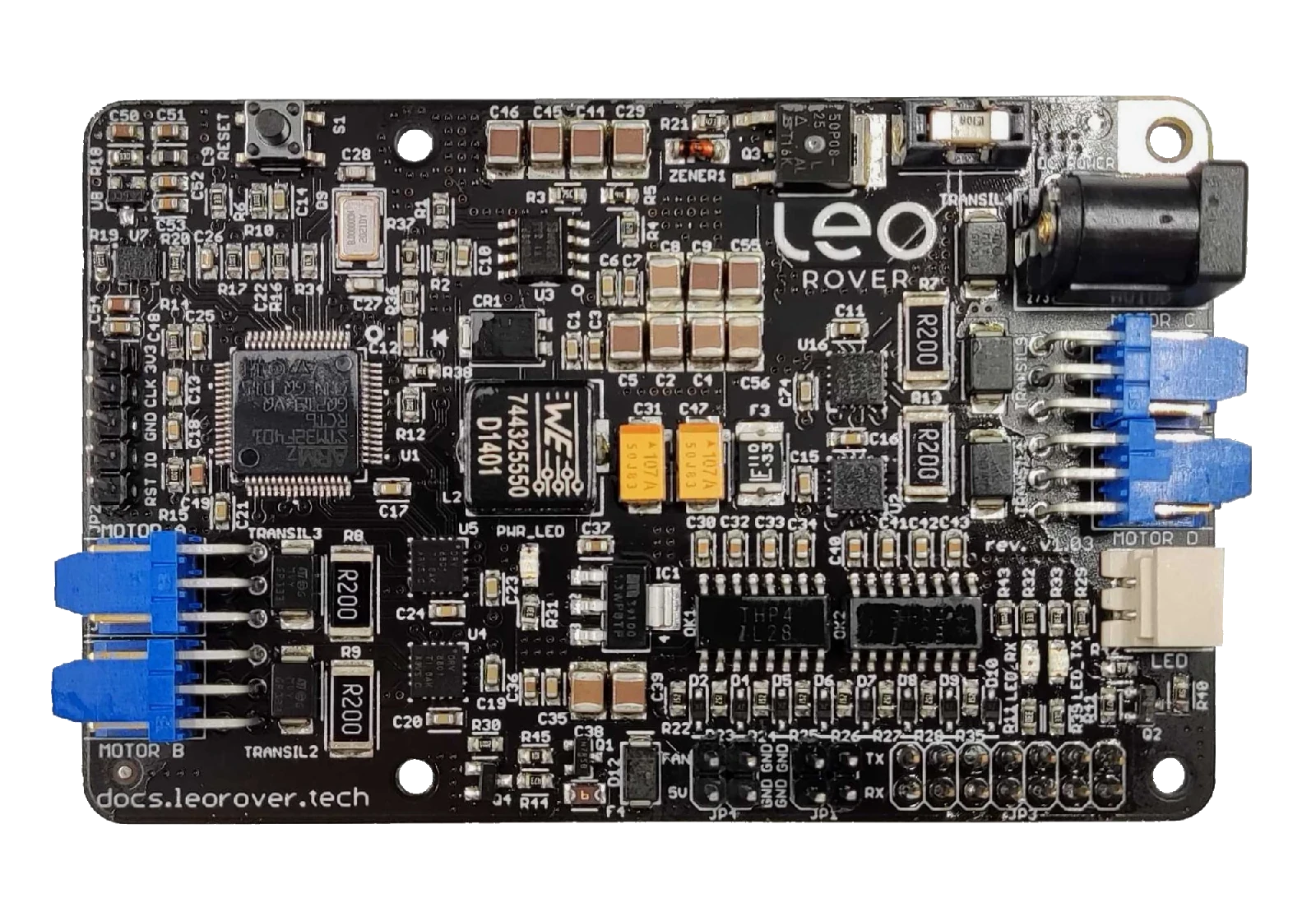
General
- Custom LeoCore board with STM32F401 microcontroller
- Works with Raspberry Pi (power + UART serial communication)
- Provides power and serial communication between LeoCore and Raspberry Pi
- Manages system readiness indicator (battery LED)
- Total current draw from all 5V outputs must not exceed 5A
- Operating temperature: -20°C to +50°C
| Port | Functionality |
|---|---|
| Power Input |
|
| Motor Outputs |
|
| LED Output |
|
| Fan Connector |
|
| GPIO Port |
|
| UART Port |
|
| Debug Port |
|
Drivetrain
The standard configuration of the Leo Rover features a drivetrain comprising four fixed wheels. This design enhances the mobility of the Rover, enabling it to execute precise maneuvers such as:
- turning in place ( around center of mass of the rover)
- turning around a curve
In addition, Leo Rover has a differential suspension system, which allows it to traverse uneven terrain and obstacles. The suspension system is designed to provide a smooth ride and maintain stability while driving over rough surfaces.
Motors
The Rover is equipped with four in-hub DC motors, each featuring a planetary gearbox with a gear ratio of 73.2:1. This configuration allows for precise control of the Rover's movement and enables it to navigate various terrains with ease. The motors are equipped with encoders that provide feedback on the wheel's position and speed, allowing for accurate control of the Rover's movement.
Wheels
As standard, Leo Rover comes with rubber tires with a diameter of about 130 mm. Whole drive assembly has following characteristics:
| Parameter | Value |
|---|---|
| Tire size (diameter x thickness) | 125 mm x 70 mm |
| Tire lock type | Non beadlock |
| Tire insert | Soft foam (non pneumatic) |
| Wheel rim diameter | 98 mm |
Battery & charging
Leo Rover is powered by a 3S2P Li-Ion battery with a total capacity of 6800 mAh. The battery is equipped with an internal battery management system (BMS) that provides protection against overcharging, over-discharging, and short circuits. The battery is designed to be easily replaceable, allowing for quick swaps during extended use.
Each battery pack has following characteristics:
| Parameter | Value |
|---|---|
| Battery type | Li-Ion |
| Battery pack type | 3S2P |
| Nominal voltage | 10.8 V |
| Charge capacity | 6.8 Ah |
| Energy capacity | 73.2 Wh |
| Maximum output power | 120 W |
| Battery cell | Samsung INR18650-35E |
| Safety systems | Overcurrent, Undervoltage, Reverse polarity, Overheat |
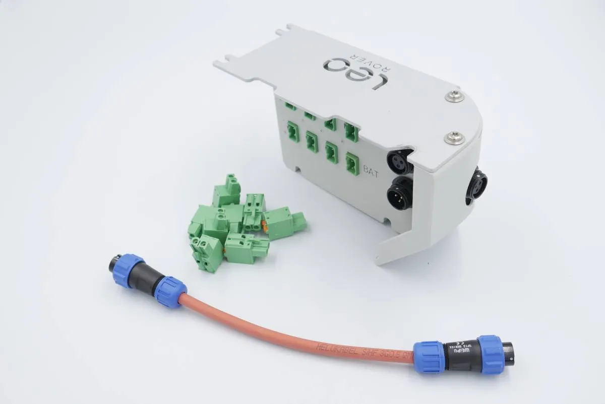
Connectors
By default Leo Rover uses standard WEIPU SP13-3 connectors for connecting battery, Main Electronics Box and other possible addons.
| Pin name | Cable color |
|---|---|
| DC- | Black |
| DC+ | Red / black with white stripe |
| LED | Green |
Battery charger
The Rover is equipped with a 2A 12.6V Li-Ion battery charger that can charge the standard battery in approximately 4 hours. The charger is designed to be compact and portable, making it easy to transport and use in various environments. The charger is equipped with a standard 5.5/2.1 mm DC plug.
The charger is outfitted with an LED status indicator designed to provide information about the charging status of the battery. A green LED signifies that the battery has reached full charge, while a red LED indicates that the battery is currently in the charging process.
| Parameter | Value |
|---|---|
| Voltage | 12.6 V |
| Current | 2 A (max) |
| Charger type | Li-Ion |
| Charger plug | DC 5.5/2.1 mm (center positive) |
| Charger adapter | Weipu SP13-3 - DC 5.5/2.1 mm |
To connect the charger to the battery, a Weipu SP13-3 - DC 5.5/2.1 mm adapter is included with each Rover. This adapter allows for easy and secure connection between the charger and the battery, ensuring that the charging process is efficient and safe.
For more information on how to charge the battery, please refer to the Leo Rover Getting started guide:
Payload specification
Leo Rover is designed to be modular and customizable, allowing users to attach various payloads and accessories to the Rover. The Rover features a mounting platform on the top, which can accommodate different payloads and accessories. The payload capacity of the Rover is approximately 5 kg, making it suitable for a wide range of applications, including research, education, and development.
| Parameter | Value |
|---|---|
| Payload capacity | 5 kg |
| Hole grid spacing | 18 mm x 15 mm |
| Mounting hole dimensions | 7 mm, equipped with T-KFS-M4-1 press-in nuts |
| Main mounting plate dimensions (L x W x D) | 299 mm x 183 mm x 2 mm |
Apart from the mounting plate, it is possible to mount payloads directly to v-slot extrusions of the Leo Rover.
In order to power the payload, we recommend purchasing a Powerbox module which replaces the additional quarter of the rover.
Software specification
Overview
Leo Rover's software heavily relies on the Robot Operating System (ROS), which offers the robot the following functionalities:
- Abstraction layer facilitating communication between software components.
- Open-source software components, maintained by the community.
- A collection of standard message interfaces.
- Tools for introspection.
The primary segment of the software stack consists of several ROS Nodes, which are computational units, each performing a single logical function. The nodes interact via:
- Topics - Named buses enabling message exchange between nodes. They are strongly typed and employ anonymous publish/subscribe semantics.
- Services - A client/server mechanism for remote procedure calls between nodes. The service server accepts remote procedure requests identified by name and type, which must be known to the service client beforehand.
- Parameters - Sets of key/value pairs maintained separately by each node, utilized for node configuration during startup and runtime without necessitating code modifications.
- TF transforms - A single transform describes the relationship between two coordinate frames at a specific point in time. TF transforms are distributed between nodes using topics, but, for the sake of clarity, we will refer to them as separate entities.
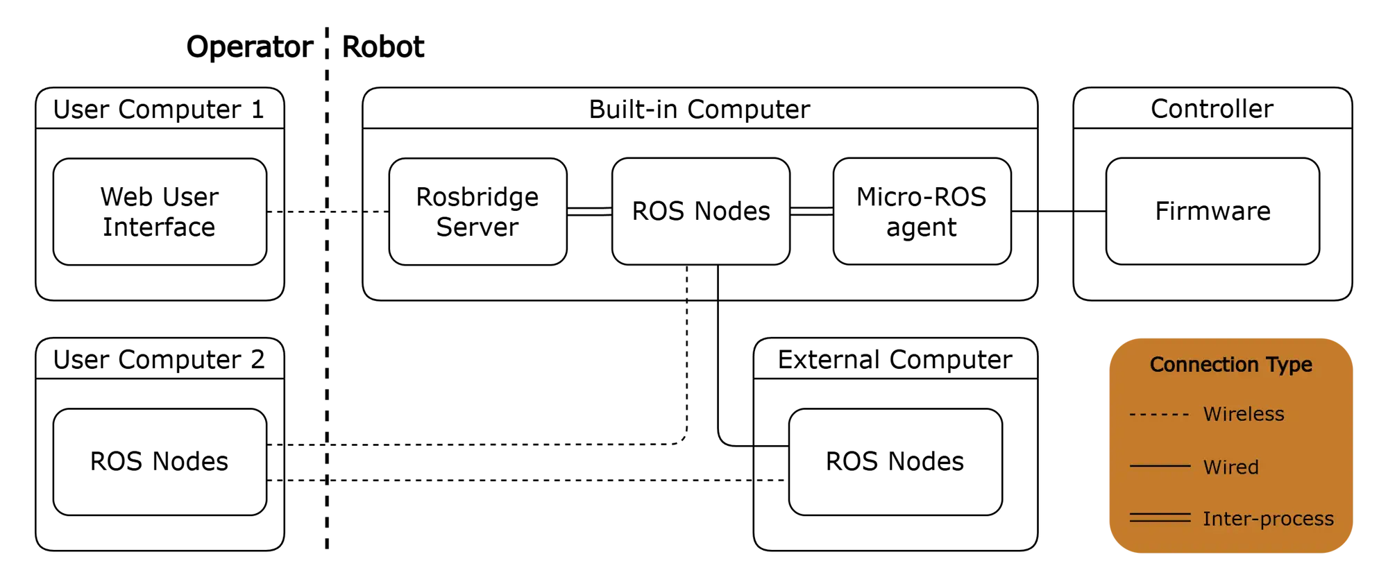
There are two important software components that don't run as native ROS nodes:
- Controller firmware - The firmware itself acts as a ROS node, but uses eProsima's Micro XRCE-DDS as its middleware. Therefore, it requires the presence of the Micro-ROS Agent on the built-in computer to communicate with other ROS nodes.
- Web User Interface - The WebUI establishes a connection with the Rosbridge Server via the WebSocket transport layer and employs the Rosbridge protocol for communication with ROS nodes.
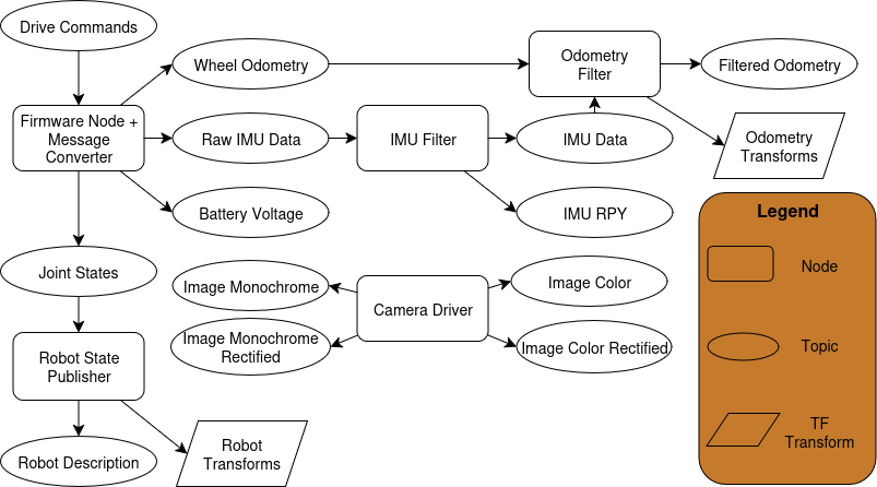
ROS nodes
| ROS Node | Description |
|---|---|
| Firmware Node | The node spawned by the LeoCore controller firmware. Allows control of the robot's wheels via topics. Additionally, it publishes relevant information, including:
|
| Robot State Publisher | Parses the kinematic tree model of the robot in URDF format and broadcasts the robot state using TF transforms. Here's how it operates:
It also publishes the robot URDF description on a designated topic, making it easily accessible to other nodes. |
| Camera Driver | Publishes camera information and various camera images, including:
All images are published at 15 FPS, both in their original resolution and in compressed versions. |
| Firmware Message Converter | Converts messages from the Firmware Node to standard ROS messages. |
| IMU Filter | Processes raw IMU data using a complementary filter which:
The gyroscope bias is periodically saved to persistent storage and loaded on startup. The node also enables calibration reset via a service. |
| Odometry Filter | Fuses wheel odometry and filtered IMU data to compute the robot's pose and velocity, and publishes this information. It can optionally broadcast an odometry TF transform and supports resetting the odometry via a service. |
| Web Video Server | Provides HTTP video streaming of ROS image topics to the Web User Interface. |
| Rosbridge Server | Provides a WebSocket interface to the ROS system, allowing the Web User Interface to communicate with ROS nodes. |
| Heading controller | Node that filters the movement commands sent to the robot to maintain a desired heading when driving straight or during wide turns. This helps the robot to better maintain its course, especially if the rubber wheels are slightly deformed. |
The names of nodes, topics, services are simplified for clarity.
For the exact names and a detailed description of the ROS Entities please refer
to the ROS API documentation.
Firmware
The "Firmware" refers to the low-level software running on the LeoCore controller. It utilizes Micro-ROS to communicate with the built-in computer via the Micro XRCE-DDS protocol and exposes functionalities such as:
- velocity commands for the robot,
- velocity and PWM commands for individual wheels,
- battery voltage feedback,
- wheel states (position, velocity, torque, PWM duty) feedback,
- odometry feedback (calculated from wheel encoders),
- feedback from the IMU sensor.
Web user interface
This is a user interface that can be accessed via a web browser. It communicates with the Rosbridge server using roslibjs to access features available on ROS topics. The default leo_ui provides features such as:
- control of the rover via a keyboard, gamepad or a virtual joystick,
- display of a camera stream from the Web video server, with the ability to select the source ROS topic for the video stream,
- display of the current battery voltage measurement,
- reboot and shutdown buttons.