How to Set Up Autonomous Navigation
This tutorial provides an example of a setup for indoor autonomous navigation on a Leo Rover. The method shown uses a 2D LiDAR and an optional stereo depth camera. For this guide, we'll use an RPLiDAR S3 and an OAK-D camera to cover the necessary steps and configurations to enable autonomous movement.
This will allow your Leo Rover to navigate autonomously in an unknown environment or navigate on a pre-made map.
Prerequisites
Firstly, you will have to connect to the Rover via SSH:
Also make sure that your Rover is connected to a local network with Internet access:
For the purpose of autonomous navigation, we prepared the leo_nav package
which makes use of many other packages available in ROS to provide autonomous
capabilities. You won't have to write a single line of code, but some
configuration may need to be tweaked to work best in your environment.
To complete this tutorial, you will need a 2D LiDAR sensor compatible with Leo Rover. You can find the list of compatible sensors here:
And optionally, you can use a compatible stereo camera for better navigation capabilities. The examples of stereo cameras compatible with Leo Rover are:
Make sure you are operating on the latest LeoOS image for the Raspberry Pi and you are up-to-date with the packages and have the newest firmware flashed.
You will also need to have ROS installed on your computer and some previous experience with ROS is recommended. To install ROS you can follow this guide:
Verifying sensor data
Before you start configuring the navigation, it's a good idea to verify that
your sensors are working correctly and publishing data. LiDAR sensors should be
publishing scan data on the ROS topic (leo_nav package uses /scan as
default), and the stereo camera (if used) should be publishing either depth data
(/oak/stereo/image_raw by default) or pointcloud data (/oak/points by
default). If there is no data being published, you should check the sensor
connections and integration. If the data is being published on a different
topic, you will need to remap the topics later.
In order to verify the sensor data from the terminal, you can use the
ros2 topic echo or ros2 topic hz commands. For example:
ros2 topic echo /scan
ros2 topic hz /oak/stereo/image_raw
Remember to also verify if the tf transformations exist for sensors. For the
system to work correctly, the base_footprint needs to have a transformation to
the sensor data frames. You can do that by running the following command:
ros2 run tf2_ros tf2_echo base_footprint laser_frame
ros2 run tf2_ros tf2_echo base_footprint oak_right_camera_optical_frame
Remember to replace laser_frame and oak_right_camera_optical_frame with the
actual frame names of your sensors.
Preparing the environment
There are a few things you will need to prepare on Leo Rover and on your computer, in order to use the software for autonomous navigation.
On Leo Rover
You will need to build the leo_nav package first. To do this, start by
accessing a remote terminal session on Leo Rover by logging in via SSH:
Create a ROS workspace if you haven't done so already:
mkdir -p ~/ros_ws/src
cd ~/ros_ws/src
Clone the leo_nav package from the Leo Rover GitHub repository:
git clone -b ros2 https://github.com/LeoRover/leo_navigation_tutorial.git
Use rosdep to install the dependencies:
sudo apt update
cd ~/ros_ws
rosdep update
rosdep install --from-paths src --ignore-src -r -y
Build the workspace:
colcon build --symlink-install
Source the workspace:
source ~/ros_ws/install/setup.bash
You will have to source the workspace on every terminal session you want to use
the package on. If you want to do it automatically upon logging into a session,
you need to modify the /etc/ros/setup.bash:
Replace the line:
source /opt/ros/jazzy/setup.bash
With:
source ~/ros_ws/install/setup.bash
On your computer
In this guide, your computer will be used for visualizing the data processed on
the rover and for sending navigation goals. For this purpose, you will need to
have the leo_description package installed on your computer.
You can install the prebuilt package from the ROS repository:
sudo apt install ros-${ROS_DISTRO}-leo-description
Remapping topics
If your sensors don't operate on the default topics, you will need to remap them when using the navigation software. All the sensor topics can be remapped by passing appropriate arguments to the launch file. This can be done when launching the navigation software from CLI or by creating a custom launch file, which can be similar to the one below:
<launch>
  <include file="$(find-pkg-share leo_nav)/launch/navigation.launch.xml">
    <arg name="scan_topic" value="/my_scan" />
    <arg name="pointcloud_topic" value="/my_pointcloud" />
    <arg name="depth_image_topic" value="/my_depth_image" />
    <arg name="depth_camera_info_topic" value="/my_depth_camera_info" />
  </include>
</launch>
Launching the software
After verifying transforms, sensor data and remapping the topics, you can launch the navigation software. Navigation software consists of two main parts: SLAM Toolbox and Navigation (Nav2) Stack. We recommend checking the SLAM Toolbox functionality first before proceeding with the Nav2 Stack and launching full navigation.
Here's the diagram of the simplified system architecture:
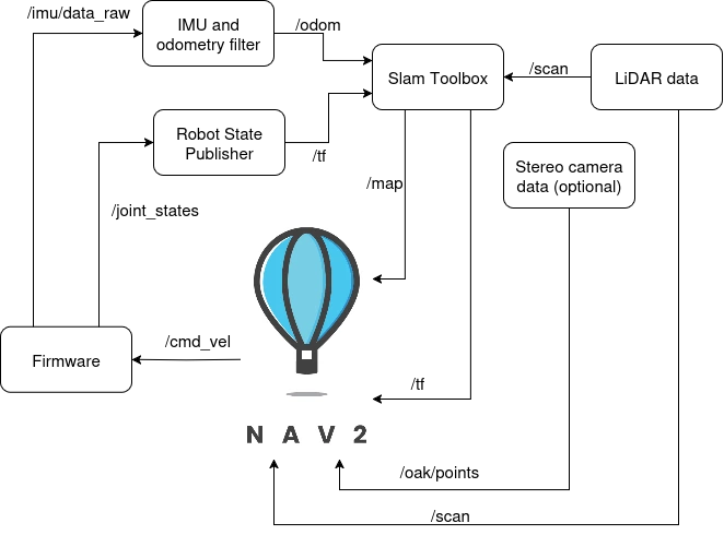
SLAM Toolbox
In leo_nav package SLAM Toolbox is used to provide
Simultaneous Localization and Mapping
capabilities. It uses the LiDAR data to create a map of the environment and
publish map -> odom transformation, which is used by the Nav2 Stack for
localization.
To launch the SLAM Toolbox on your Leo Rover you can use the provided launch file:
ros2 launch leo_nav slam_toolbox.launch.py
If you have LiDAR scans on a different topic than /scan, you will need to
remap it When launching SLAM Toolbox:
ros2 launch leo_nav slam_toolbox.launch.py scan_topic:=/your_lidar_topic
The SLAM Toolbox node takes as the input:
- laser scan data from the LiDAR sensor (default topic:
/scan), - position of the laser reference frame (
base_footprint -> laser_frametransform), - current position of the robot from the odometry (
odom -> base_footprinttransform).
As the output, it publishes:
- a map of the environment in form of an occupancy grid (
/mapand/map_metadatatopics), - current odometry drift based on the estimated position of the robot within the
map (
map->odomtransform).
When the SLAM Toolbox node tries to correct robot's position within the map, it
does not broadcast the position as the map -> base_footprint transform,
because that would make 2 root coordinate frames (map and odom). Instead, it
provides the map -> odom transform which marks the difference between the
odometry position and the actual position of the robot within the map (the
odometry drift).
You can now visualize the SLAM process in RViz2. This step needs to be done from your computer. To do this, first source ROS and then launch RViz2 with the following command:
source /opt/ros/<your_ros_distro>/setup.bash
rviz2
In RViz2, you can add the following displays to visualize the SLAM process:
- Map: Displays the map created by SLAM Toolbox.
- LaserScan: Displays the LiDAR scans being used for mapping.
- RobotModel: Displays the robot model.
Remember to choose the correct fixed frame in RViz2, which should be set to
map for SLAM Toolbox. Also don't forget to set the correct topics for the
displays.
The view in RViz2 should look similar to this:
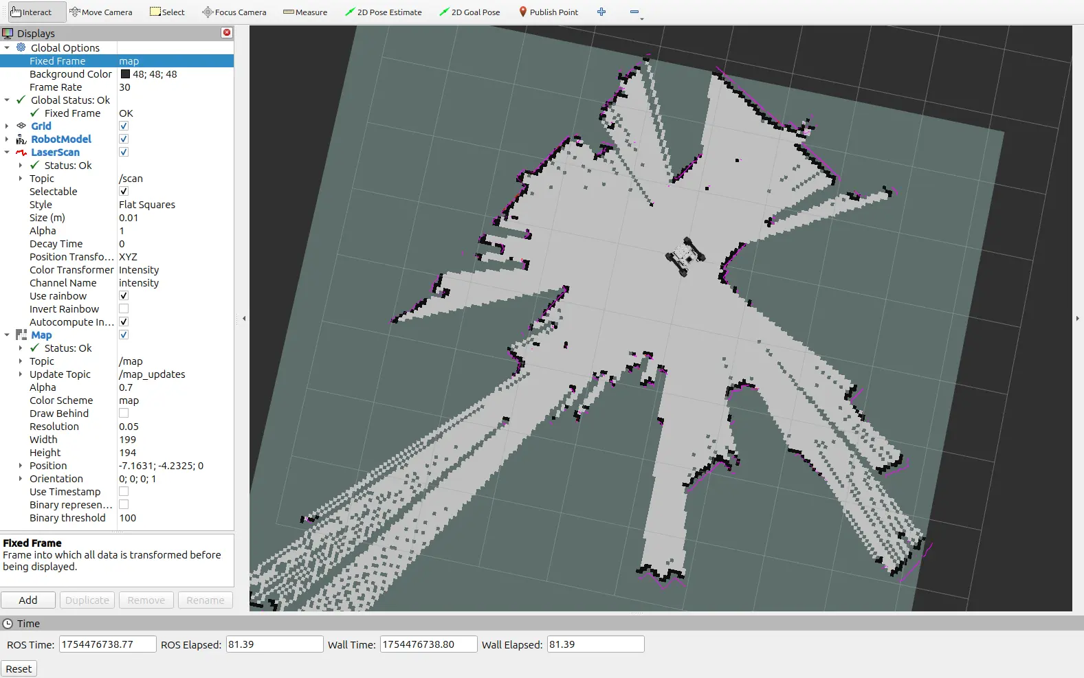
If you see both the map and the LiDAR scans, it means that SLAM Toolbox is working correctly.
Configuration
The configuration for the SLAM Toolbox node is loaded from the
config/slam_toolbox.yaml file. For description of each parameter visit the
SLAM Toolbox GitHub repository
Changing the parameters in a way that results in higher computational load may lead to violation of the real-time constraint. This in turn can make the algorithms perform even worse.
Navigation (Nav2 Stack)
After you have verified that SLAM Toolbox is working correctly, you can proceed to launch the Nav2 Stack. You can find information about Nav2 Stack in the official documentation.
Nav2 stack in leo_nav package consists of:
- Planner Server: responsible for planning the path to the goal.
- Controller Server: responsible for controlling the robot to follow the planned path.
- Behavior Tree Navigator: responsible for managing the navigation process and executing the navigation tasks.
- Waypoint Follower: responsible for following the waypoints in the planned path.
- Lifecycle Manager: responsible for managing the lifecycle of the navigation components.
The architecture of the Nav2 Stack is shown in the diagram below:


These components work together to provide autonomous navigation capabilities for the Leo Rover.
To launch the Nav2 Stack in its default configuration, you can use the provided launch file:
ros2 launch leo_nav navigation.launch.xml
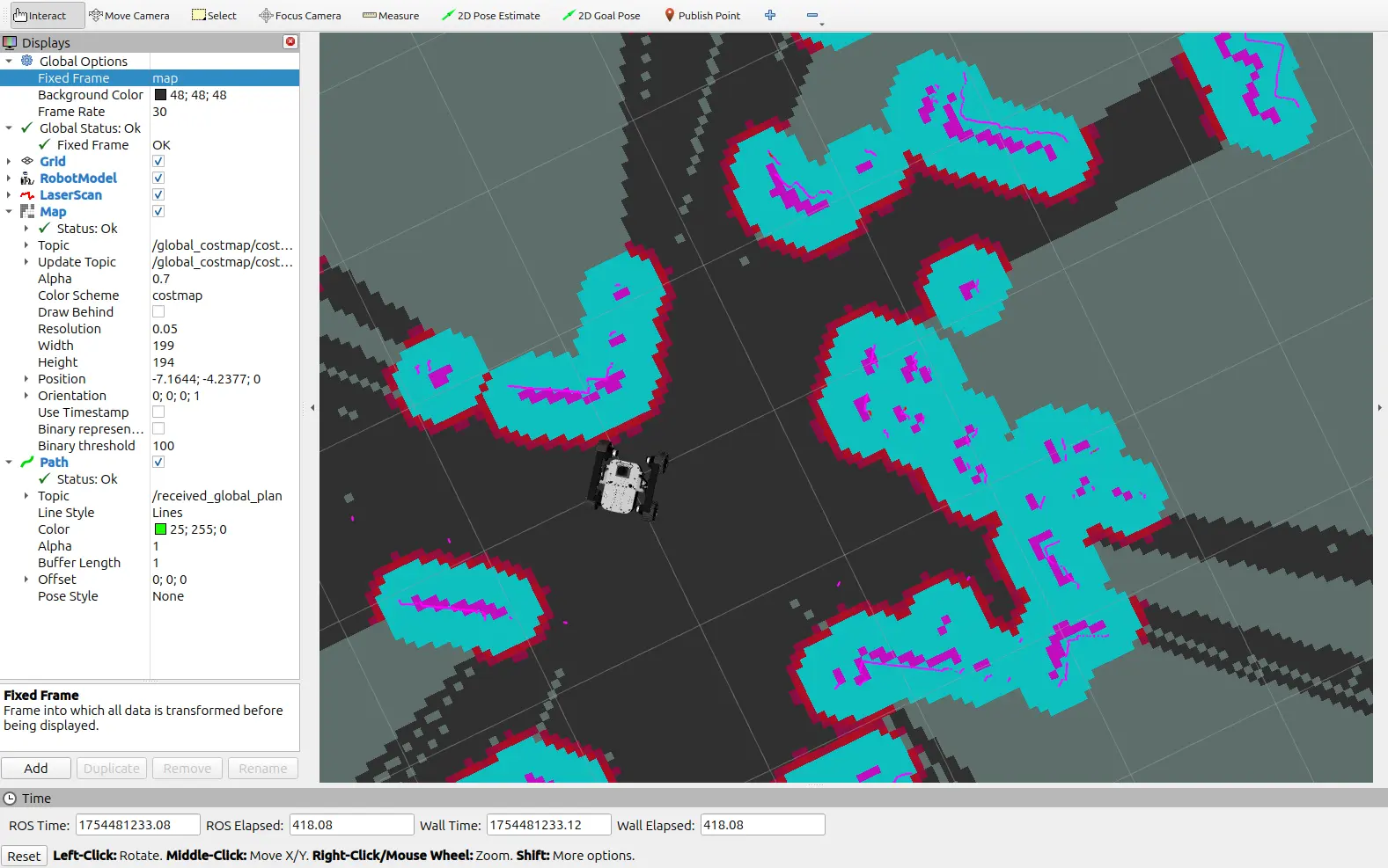
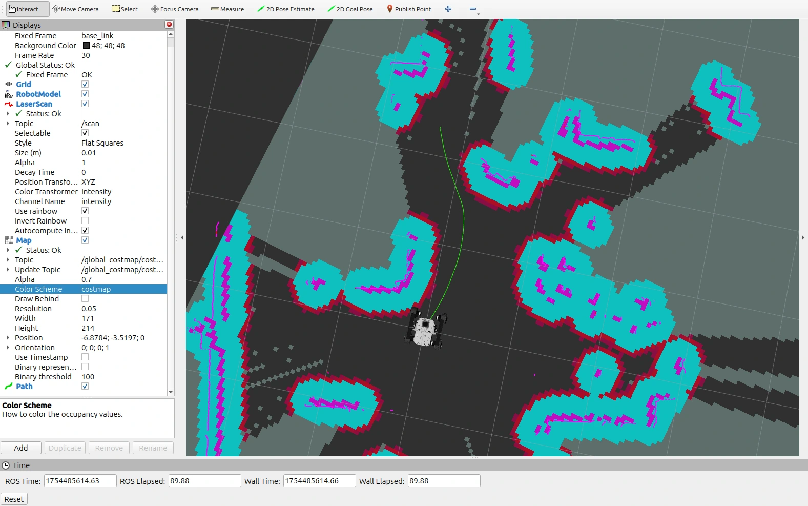
Now, on your computer, you can launch RViz2 again and add the following displays to visualize the navigation process:
- Map on topic
/global_costmap/costmap: Displays the global map created by Nav2. For better clarity, change the color scheme tocostmap. - LaserScan on your scan topic (
/scanby default): Displays the LiDAR scans being used for navigation. - RobotModel: Displays the robot model.
- Path on topic
/received_global_plan: Displays the planned path to the goal.
After setting fixed frame to map, your RViz2 view should look similar to this:
Now, to send a navigation goal from RViz, select the 2D Goal Pose tool from the toolbar (highlighted in the image below) located at the top, then click somewhere on the map to set position or click and drag to set position and orientation.
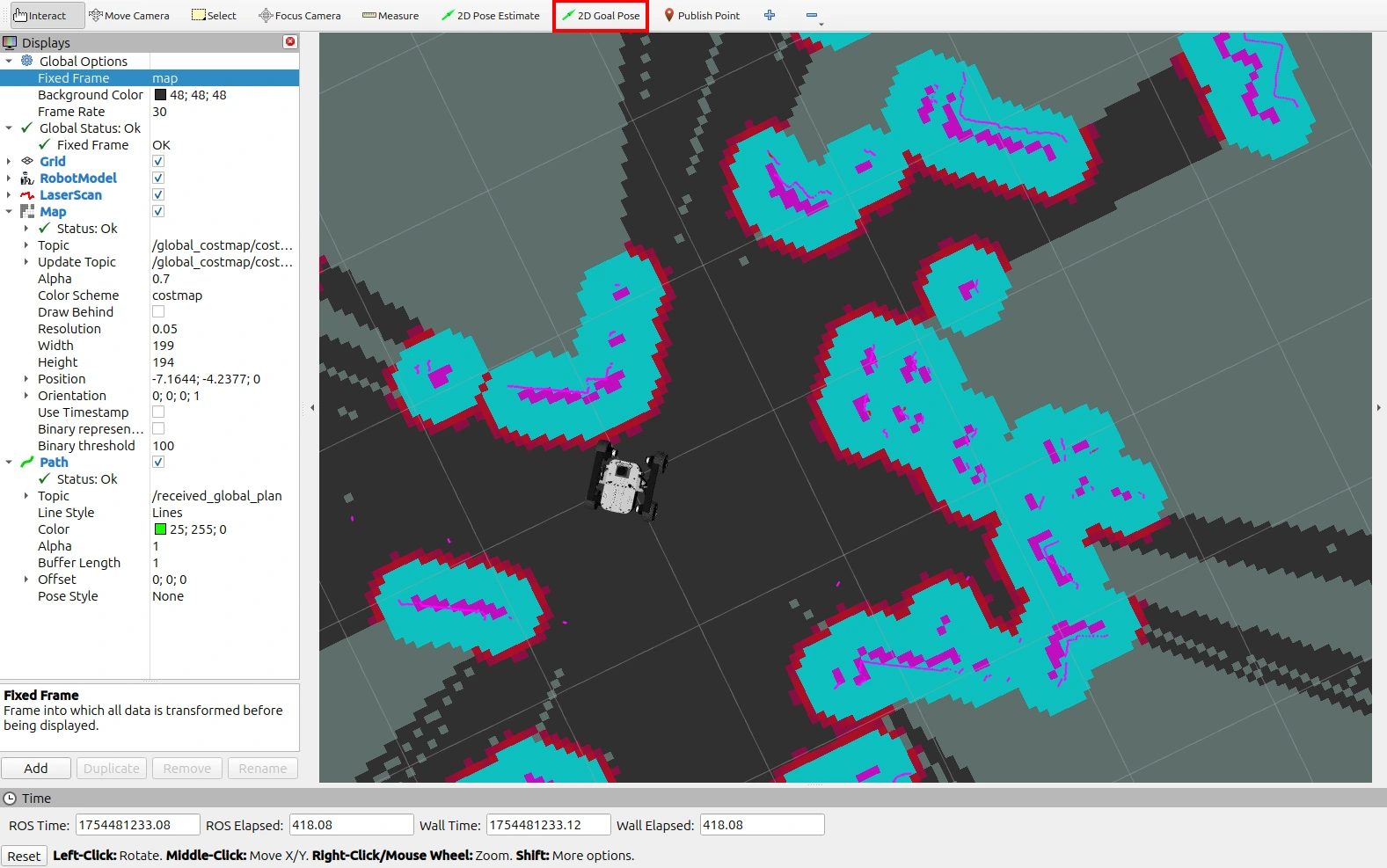
Provided you clicked on a valid position, the robot should start moving towards the goal. The path should now be visible in RViz2, and the robot should follow it.
Congratulations! You can now control your Leo Rover using the Nav2 Stack and send navigation goals from RViz2.
Configuration
Nav2 configuration can be found in the config/navigation.yaml file. You can
change the parameters to better suit your needs, but consult every change with
the official
Nav2 configuration guide
first.
The navigation.launch.xml file contains different arguments that can be used
to customize the navigation system. Available launch arguments are:
localization: Whether to use SLAM Toolbox in mapping mode (when set to false) or AMCL for localization only (when set to true) (default:false).slam_params_file: Path to the SLAM parameters file (used if localization is false, default:/config/slam_toolbox.yaml).amcl_params_file: Path to the AMCL parameters file (used if localization is true, default:/config/amcl.yaml).map_file: Path to the map file (required for AMCL - when localization is true, default:/maps/empty_map.yaml). It has to be a valid map file in YAML format with a corresponding PGM image file.use_stereo_camera: Whether to enable stereo camera nodes and configurations (default: false).navigation_params_file: Path to the navigation parameters file (default:/config/navigation.yamlfor standard navigation, or/config/navigation_stereo_camera.yamlfor stereo camera based navigation).scan_topic: Topic for laser scan data (default:/scan).pointcloud_topic: Topic for point cloud data (default:/oak/points).depth_image_topic: Topic for depth image data (default:/oak/stereo/image_raw).depth_camera_info_topic: Topic for depth camera info data (default:/oak/stereo/camera_info).
To launch the navigation with changed arguments, use syntax
<arg_name>:=<value>. For example, in order to use a stereo camera use:
ros2 launch leo_nav navigation.launch.xml use_stereo_camera:=true
AMCL localization
AMCL is used in the
leo_nav package to provide localization capabilities when the robot is already
mapped. It replaces the SLAM Toolbox in the navigation process when the
localization argument is set to true in the navigation.launch.xml file. Its
configuration can be found in the config/amcl.yaml. To get more information
about the parameters, visit the
AMCL documentation.
To launch the navigation system with AMCL localization, use the following command:
ros2 launch leo_nav navigation.launch.xml localization:=true map_file:=/path/to/your/map.yaml
This will replace the SLAM Toolbox with AMCL and use the provided map file for
localization. The map can be obtained for example by running the SLAM Toolbox in
mapping mode and saving the map using the built in map_saver wrapper:
ros2 service call /slam_toolbox/save_map slam_toolbox/srv/SaveMap "{name: {data: 'map_name'}}"
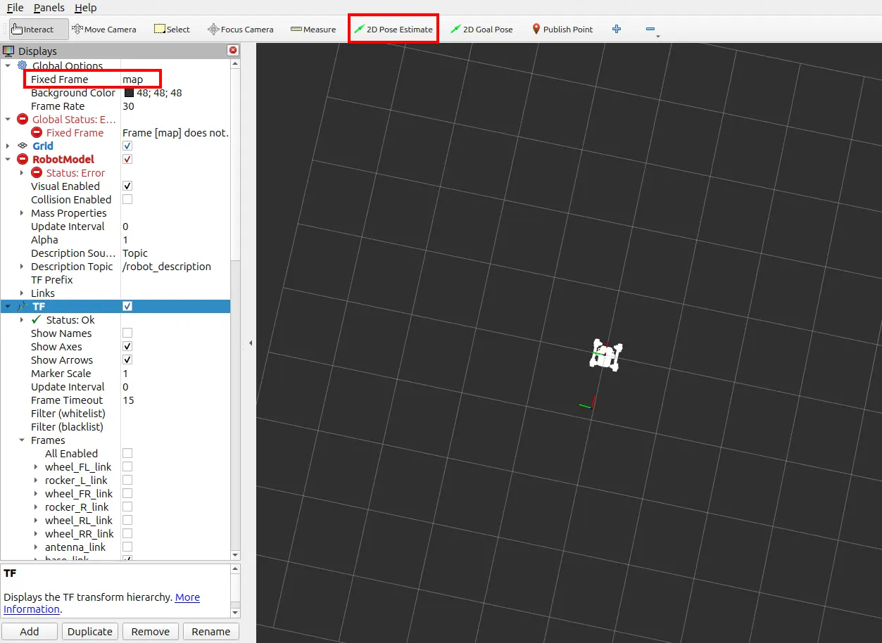
For AMCL to start working, you need to specify the estimated position of the
robot in the map. You can do this by setting the initial pose in RViz2 using the
2D Pose Estimate tool (highlighted in the image below) located at the top of the
RViz2 window. Remember to change the fixed frame to map before setting the
initial pose.
The initial pose can also be set by publishing a
geometry_msgs/PoseWithCovarianceStamped message on the /initialpose topic or
by setting the set_initial_pose parameter to true and initial_pose to the
desired pose in the AMCL configuration file. It is also possible to set the pose
multiple times, AMCL will update the initial pose each time you set it.
After setting the initial pose, AMCL should start publishing the
map->base_footprint transform and the errors visible in RViz2 should
disappear. If that is the case, you can send navigation goals as before, and the
robot should be able to localize itself and navigate to the goal using the
provided map.
Don't worry if you have minor inaccuracies in the initial pose, AMCL will correct them over time as it receives more sensor data when the robot moves. However, the better the initial pose, the more accurate the localization will be from the start.