Ouster LiDAR
This tutorial will guide you through the process of connecting and using Ouster LiDAR sensor on your rover. This tutorial will use Ouster OS0, however the integration process is the same for other models such as OS1 and OS2.
Light Detection and Ranging devices, or Lidars for short, are mechanisms used for mapping the environment, object detection, tracking the speed of vehicles and in a wide range of other applications. Ouster devices excel at 3D scanning near-range distances within dense, cluttered environments. The OS2 has a range of 100 m, and the sensor's light weight (522 g), compact footprint (~Ø87 mm x 58 mm), and 90 degree vertical field of view make it ideal not only for autonomous vehicles but also robotics and mobile 3D mapping applications.
What to expect?
After finishing the tutorial you will have configured the Ouster LiDAR to work on your rover. You will be able to gather and visualize the data from the sensor.
Prerequisites
Mechanical integration
Work in progress
Wiring and electronics connection
Work in progress
Software integration
Setting up the Ouster sensor on the rover
Make sure that the sensor is properly plugged in and the ethernet cable is connected to the ethernet port on the rover's Raspberry Pi.
Now the sensor will get an IP assigned by rover's DHCP server. However the
device will associate this IP address with custom hostname, which is
os-sensor_serial_number (e.g. os-111222333444). You can find the
serial number on top of your sensor. Alternatively you can scan the QR code that
you can find on your device to get information about the serial number.
To ensure that the device has been connected successfully you can enter Ouster
sensor dashboard. To do so open your browser of choice on a computer connected
to rover's WiFi and go to address: os-sensor_serial_number.local
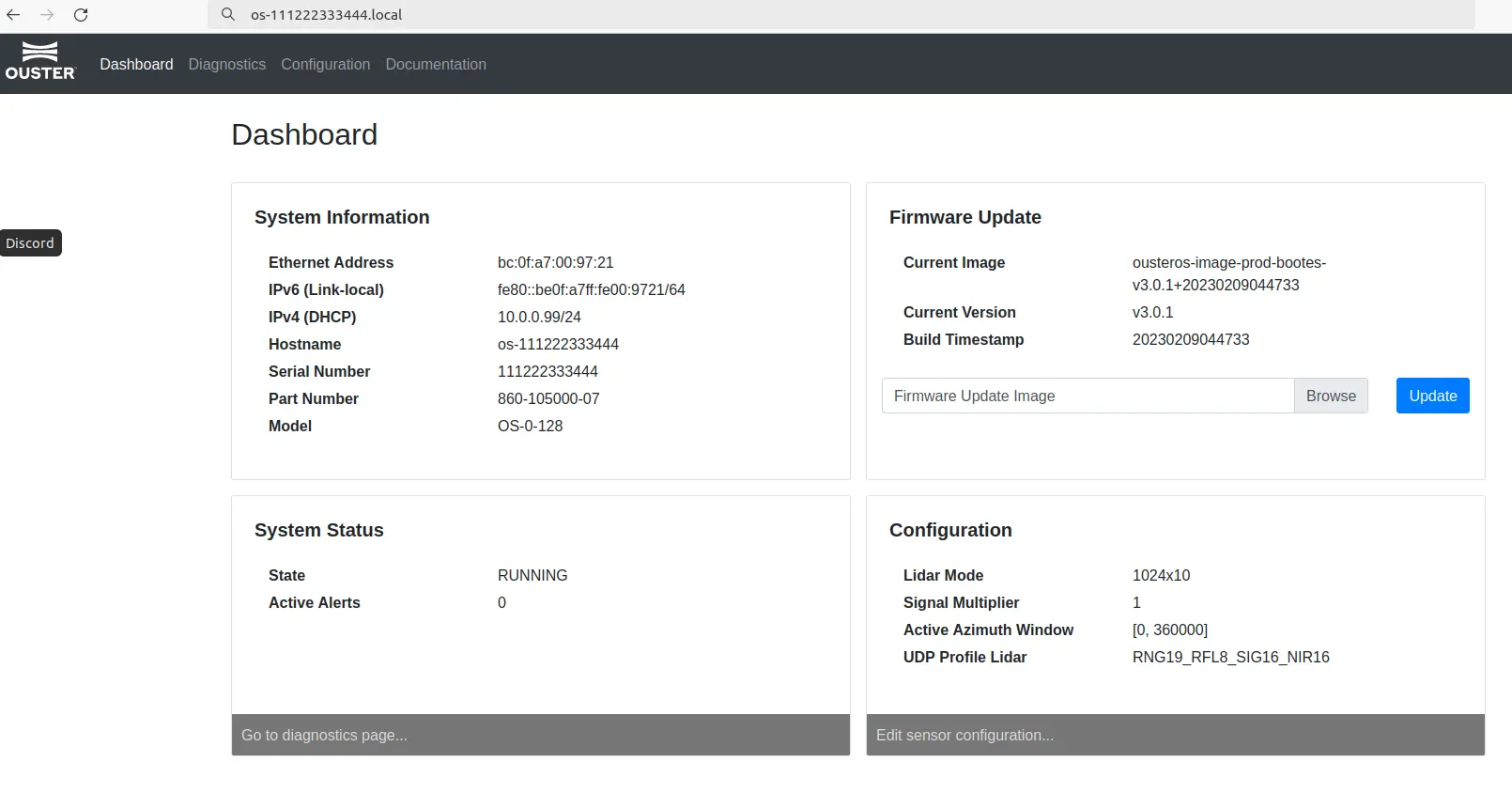
For more information about the sensor web interface visit Ouster Docs.
On this page you can view information about the device and configure it. This tutorial doesn't require changing anything in this configuration.
If you wish to change Ouster sensor configuration, you can do so later - when configuring ROS node, as this node can overwrite some changes made inside the web interface.
ROS software installation
Ensure that your rover is connected to the internet.
Make sure that system date is correct by writing this command in the terminal.
date
If the date is not correct you can set it to current date. Replace
YYYY-MM-DD HH:MM:SS with current date and time e.g. 2023-01-31 09:00:00.
sudo date -s 'YYYY-MM-DD HH:MM:SS'
Next make sure that all your packages are up to date.
sudo apt update && sudo apt upgrade
Now you can install all required dependencies.
sudo apt install -y       \
  build-essential         \
  libeigen3-dev           \
  libjsoncpp-dev          \
  libspdlog-dev           \
  libcurl4-openssl-dev    \
  cmake
If you haven' t already, setup a ROS workspace.
mkdir -p ~/catkin_ws/src
cd ~/catkin_ws
catkin init
Go to the src directory in your workspace and clone a repository with Ouster
ROS driver and SDK.
cd ~/catkin_ws/src
git clone --recurse-submodules https://github.com/ouster-lidar/ouster-ros.git
Next to compile the driver you need to source the ROS environment into the
active terminal. Replace <ros-distro> with your ROS version e.g. noetic.
source /opt/ros/<ros-distro>/setup.bash
You can now build your workspace.
cd ~/catkin_ws
catkin build --cmake-args -DCMAKE_BUILD_TYPE=Release -- -j1 -l1
In order to achieve better driver performance, the packages are built with Release build type flag. This results in a longer build time that can take up to several minutes.
Running Ouster driver ROS node
To run the node first source the workspace.
source ~/catkin_ws/devel/setup.bash
Then you can launch the driver. Remember to enter the correct hostname with your sensor's serial number.
roslaunch ouster_ros driver.launch sensor_hostname:=os-xxxxxxxxxxxx viz:=false
If you get an error while launching the node, make sure that the hostname has
been properly set. To do that you can try: ping os-xxxxxxxxxxxx. If you get a
Name or service not known error, try unplugging the sensor ethernet cable and
plugging it back in.
For more information on ouster driver and parameter details head to this GitHub page.
Adding Ouster sensor to URDF
Your robot should be aware of where the sensor is located and what space it
occupies. You can ensure it does that by creating an URDF model file of the
sensor in /etc/ros/urdf directory.
<?xml version="1.0"?>
<robot>
    <joint name="ouster_mount_joint" type="fixed">
      <parent link="base_link"/>
      <child link="ouster_base_link"/>
      <origin xyz="0.0705 0 0"/>
    </joint>

    <link name="ouster_base_link" />

    <joint name="ouster_base_to_baseplate" type="fixed">
      <parent link="ouster_base_link"/>
      <child link="ouster_baseplate" />
      <origin xyz="0 0 0.0045"/>
    </joint>

    <link name="ouster_baseplate">
      <visual>
        <geometry>
          <box size="0.087 0.095 0.009" />
        </geometry>
        <material name="silver">
          <color rgba="0.5 0.5 0.5 1.0" />
        </material>
      </visual>
      <collision>
        <geometry>
          <box size="0.087 0.095 0.009" />
        </geometry>
      </collision>
    </link>

    <joint name="ouster_baseplate_to_body" type="fixed">
      <parent link="ouster_baseplate"/>
      <child link="os_sensor"/>
      <origin xyz="0 0 0.042" rpy="0 0 0" />
    </joint>

    <link name="os_sensor">
      <inertial>
         <mass value="0.33"/>
         <origin xyz="0 0 0.0365" rpy="0 0 0" />
         <inertia ixx="0.000241148" ixy="0" ixz="0"
          iyy="0.000241148" iyz="0" izz="0.000264"/>
      </inertial>
      <collision name="base_collision">
         <origin xyz="0 0 0" rpy="0 0 0" />
         <geometry>
           <cylinder radius="0.04" length="0.073"/>
         </geometry>
      </collision>
      <visual name="base_visual">
         <origin xyz="0 0 0" rpy="0 0 0" />
         <geometry>
           <cylinder radius="0.04" length="0.073"/>
         </geometry>
      </visual>
    </link>

    <link name="os_imu" />

    <link name="os_lidar" />


    <joint name="os_imu_link_joint" type="fixed">
      <parent link="os_sensor" />
      <child link="os_imu" />
      <origin xyz="0.006253 -0.011775 0.007645" rpy="0 0 0" />
    </joint>

    <joint name="os_lidar_link_joint" type="fixed">
      <parent link="os_sensor" />
      <child link="os_lidar" />
      <origin xyz="0.0 0.0 0.03618" rpy="0 0 0" />
    </joint>
</robot>
And including it inside the <robot> tag in the description file that is
uploaded at boot.
<xacro:include filename="/etc/ros/urdf/ouster.urdf.xacro"/>
You can experiment with the URDF file and create a more representative model of the sensor by adding more visual and collision tags or by including meshes in STL or COLLADA format. You can find the Ouster description files here.
The last step is to either reboot the robot or restart the leo service.
sudo systemctl restart leo
Adding the node to autostart
Open /etc/ros/robot.launch and add below line inside <launch> tag. Remember
to enter your device's serial number in sensor_hostname value field.
<include file="$(find ouster_ros)/launch/driver.launch">
  <arg name="sensor_hostname" value="os-xxxxxxxxxxxx" />
  <arg name="viz" value="false" />
</include>
Next, open /etc/ros/setup.bash and below source /opt/ros/noetic/setup.bash
add:
source /home/pi/catkin_ws/devel/setup.bash
Now you can reboot the robot or restart the leo service
sudo systemctl restart leo
Examples
If the node is running, the robot should publish the PointCloud2 messages on
the /ouster/points topic. You can check the raw data that it sends by typing:
rostopic echo /ouster/points
If you have ROS installed on your computer, you can get a more graphical representation of the data with RViz. If you don't have ROS, you can follow this guide:
Before starting RViz, make sure you completed the Connecting another computer to ROS network section of ROS Development tutorial:
Now, open RViz by typing rviz in the terminal, or, if you have the leo_viz
package installed, type:
roslaunch leo_viz rviz.launch
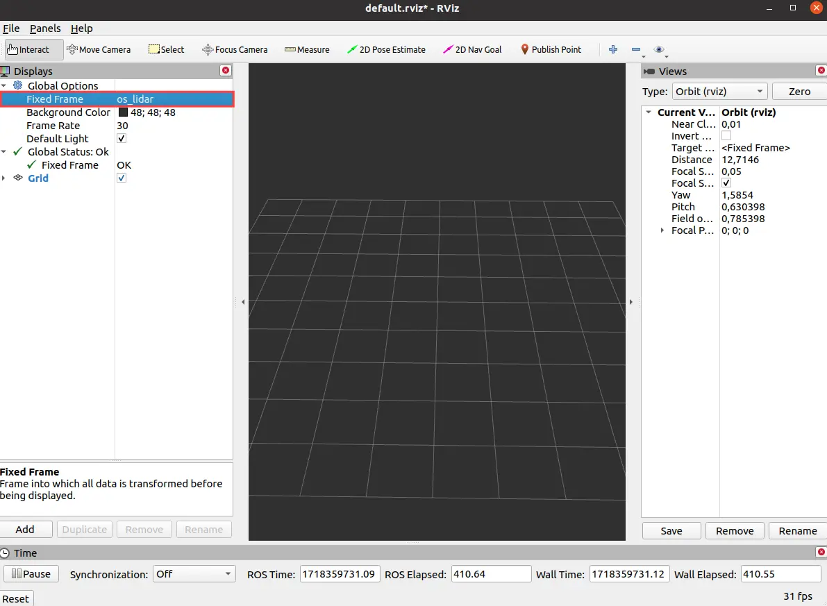
This will start RViz with visualization of the current robot model.
In Global Options change Fixed Frame to os_lidar.
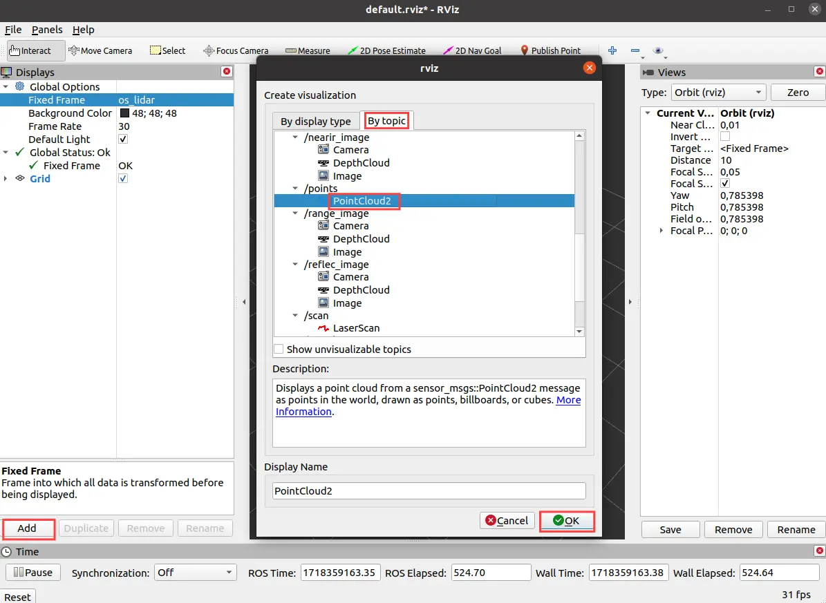
On the Displays panel click Add -> By topic and search for the
/ouster/points topic. Choose the PointCloud2 display and click Ok.
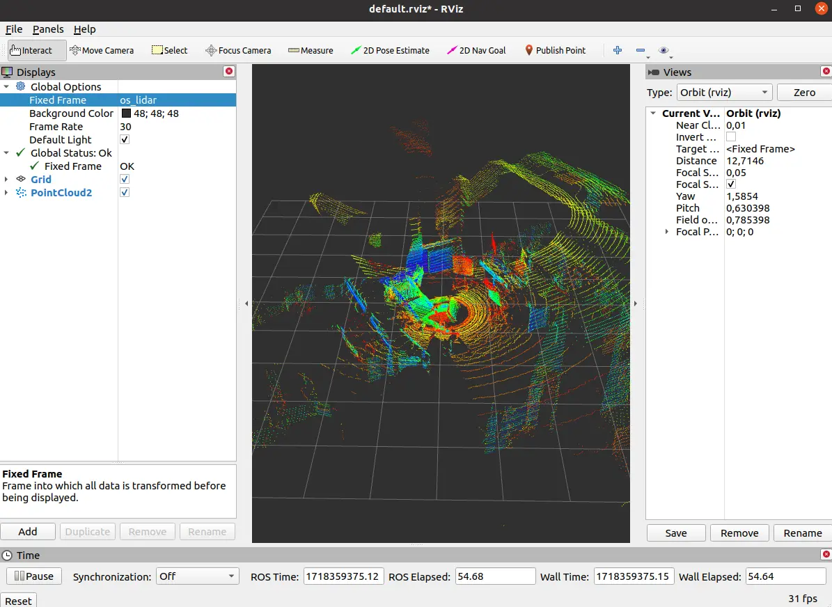
Visualized pointcloud should look like this:
What next?
Lidars are commonly used in projects involving autonomous navigation, you might be interested in a tutorial about it.
They are however, not the only way of teaching a Leo Rover how to move on it's own. Check out our line follower tutorial if you want to learn more. You can also check our Integrations page for more instructions.