Grove IMU
Since Leo Rover v1.8 IMU is already integrated into LeoCore controller. You don't have to integrate it.
This integration is not compatible with Leo Rover v1.8. It is kept on site for legacy purposes.
In this tutorial, we will show you how to connect and use a Grove inertial measurement unit module on your Rover.
Prerequisites
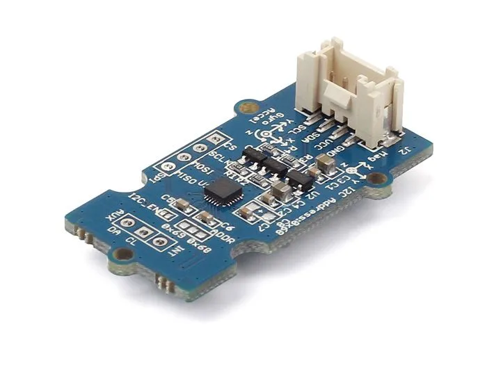
First, make sure you have a compatible IMU module. The firmware supports only
the MPU-9250 sensors. We recommend the Grove - IMU 9DOF v2.0 board but
most modules with this sensor should work.
IMU functionality was introduced in leo_firmware version 0.5, so make sure to stay updated.
Mounting and wiring the sensor
By default, the IMU will work on hSense2 port. You can change it to hSense1
by modifying the
params.h file
in leo_firmware.
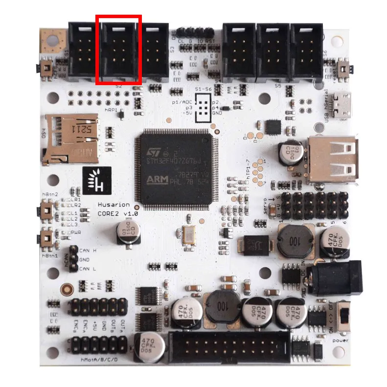
Connect the sensor pins according to the CORE2 manual.
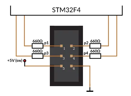
| hSense pin | IMU pin |
|---|---|
| 3 | SCL |
| 4 | SDA |
| 5 | +5V |
| 6 | GND |
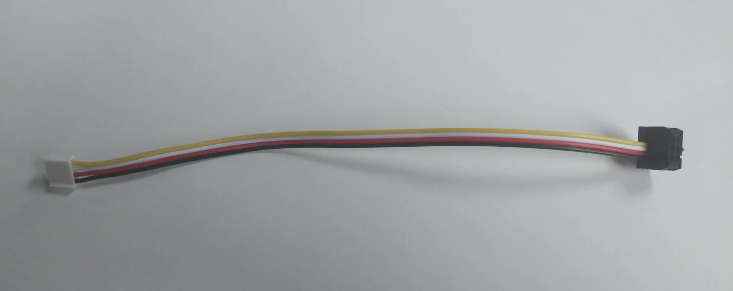
You can use female jumper cables, or create your own IDC cable, like this one:
If you use the Grove IMU, you can 3D print the mounting plate for the MEB cover which contains holes for the self-tapping screws (00189_imu part). The files can be found here:
Integrating the sensor with the system
Turning on the IMU functionality
Start a remote terminal session on the Rover via SSH.
To set IMU functionality on or off, you need to call the /core2/set_imu
service.
rosservice call /core2/set_imu true
Now, you need to reset the board to apply changes. You can do this by turning on
and off the whole Rover, or by calling the /core2/reset_board service:
rosservice call /core2/reset_board
After the board reset, new topics should spawn: /imu/gyro, /imu/accel,
/imu/mag on which IMU gyroscope, accelerometer and magnetometer readings are
published (you can check available topics with rostopic list).
Check if the readings are correct with rostopic echo, for example:
rostopic echo /imu/gyro
Sensor axes and units
The sensor's accelerometer and gyroscope X, Y and Z axes should be printed on the board. If they are not, you can check MPU9250 IC orientation and identify the axes with this drawing:
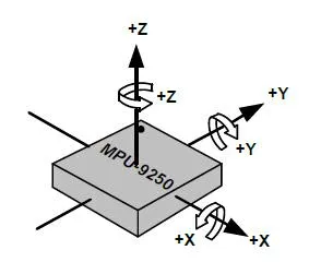
The magnetometer axes were also transformed to these axes to comply with the North-West-Up world frame.
The gyroscope data (imu/gyro topic) represents angular velocity around
sensor's axes in rad/s (radians per second). The accelerometer data (imu/accel
topic) represents linear acceleration along sensor's axes in m/s2 (meters per
second squared). The magnetometer data (imu/mag topic) represents magnetic
field along sensor's axes in G (Gauss).
Extending the URDF model
The system should be aware of where the module is located on the robot in order
to be able to use the sensor readings. To specify the location, you can extend
the URDF model of Leo Rover by editing the /etc/ros/urdf/robot.urdf.xacro.
Simply open the file in nano editor by typing:
nano /etc/ros/urdf/robot.urdf.xacro
Add these lines somewhere between the <robot> tags:
<link name="imu"/>

<joint name="imu_joint" type="fixed">
  <parent link="base_link"/>
  <child link="imu"/>
  <origin xyz="0.027 0 -0.07" rpy="0 0 0"/>
</joint>
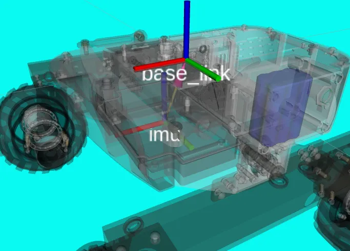
imu link represents the reference frame of the sensor readings.
base_link is the origin of the robot.
imu_joint specifies the transformation between these two links.
You might need to modify the transformation (<origin> tag) depending on how
you mounted the module.
For more information, visit ROS Development -> Adding additional functionality to the rover -> expanding the URDF model
After modifying the description, restart the nodes to apply the changes:
sudo systemctl restart leo
To check if it's working correctly, you can check for the transformation between
base_link and imu frames:
rosrun tf tf_echo base_link imu
Calibrating the sensor
The firmware also provides services that perform sensor calibration and store the results in a persistent storage.
Calibrate gyroscope and accelerometer biases
To calibrate gyroscope and accelerometer biases, just place the Rover on a flat surface, parallel to the ground and call the calibration service:
rosservice call /imu/calibrate_gyro_accel
Calibrate magnetometer
Calibrating the magnetometer is a bit more difficult task, as it requires collection of a whole range of measurements on each axis. The method that works best is to move the sensor in a 3-dimensional figure eight, however, such motion can be hard to accomplish with the whole Rover.
To start the calibration, just call the service:
rosservice call /imu/calibrate_mag
After 4 seconds, the firmware should start data collection. After another 15 seconds, the service should return success message. Try to move the sensor in a varied motion for the whole duration of the service call.
When you change the sensor position on the Rover, the hard-iron distortion may change and invalidate previous calibration data, so, before performing the magnetometer calibration, make sure the sensor is located at the designated place