Fixposition Vision-RTK 2 GPS
This tutorial will guide you through the process of connecting Fixposition Vision-RTK 2 to Leo Rover.
Fixposition Vision RTK2 is a great GPS module capable of achieving up-to a centimeter-level accuracy. This system leverages Real-TimeKinematic (RTK) and vision-based positioning technology to provide precise localization even in challenging environments. With its compact design Vision-RTK 2 empowers Leo Rover users to navigate with unparalleled accuracy, unlocking new possibilities for research, exploration, and industrial applications.
What to expect?
Prerequisites
List of components
- Fixposition Vision-RTK2
- Power connector
- Adapter plate (eg. the one we provide here)
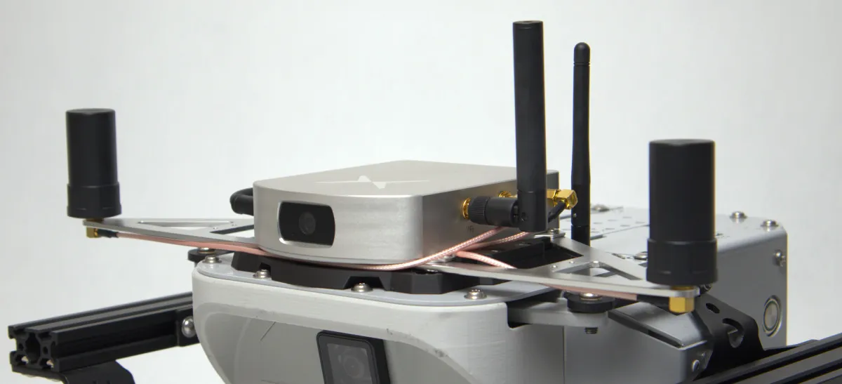
Mechanical integration
The module needs to be attached to the rover in a spot that provides an uninterrupted view of the terrain.
The accuracy of the system depends on how far apart the GNSS antennas are spaced. Since Leo Rover is rather small it might be hard to place them more than 30cm apart. The system provides a satisfactory accuracy with setup like this, but it's not advised to go even lower. If your project allows it, try to position the antennas even further apart. It's also a good choice to move the GNSS antennas away from any parts of the rover that might be a source of electromagnetic interferences (e.g. motors).
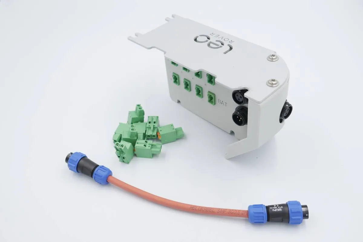
Wiring and electronics connection
The only wire needed for the module to work is a power cable. An external power distribution module like our Powerbox might come in handy in this case. Connecting the power wire straight to the rovers battery is theoretically possible, but not advised.
Software integration
Before starting the software integration, please make sure that the sensor is properly configured. It's good to check out the integration instruction and follow 4th and 5th chapters, as well as the quick start guide.
In the network configuration part, you need to connect the sensor to the rover's access point, to establish data flow between Vision RKT-2 and the Leo robot.
It's also worth to remember the sensor's IP address at this point, as it's clearly visible in the fixposition's web UI.
Having configured the sensor, and connected to the rover, the only thing that we need to do is integrate the sensor's data into ROS system running on the rover.
For this task we need to install the fixposition ROS driver into our ROS workspace, therefore log in using ssh to the rover, and enter the directory with package sources in your workspace:
cd <your_workspace>/src
Then download the GitHub repository with the driver:
git clone https://github.com/fixposition/fixposition_driver.git
As the repository also contains sources of packages for ROS2 we can remove them:
cd fixposition_driver
rm -rf *ros2
Now we need to build the package, so go back to the ROS workspace and execute those commands:
rosdep update
rosdep install --from-paths src -iry
catkin build
Once the packages are installed, we need to do some configuration for the driver
to work properly. First we have to change the ip parameter in the tcp.yaml
file to the sensor's IP address in the rover network, so it should look like
this:
ip: '10.0.0.137'
As we are going to provide wheel odometry data for the sensor from our robot, we
have to configure also the odometry converter. In theodom_converter.yaml file
we have to put the correct topic type and name and chose to use the angular data
from the topic too. We will use the/odometry_merged topic of type Odometry
with the angular data, therefore the parameters will be:
topic_type: 'Odometry'
input_topic: '/odometry_merged'
use_angular: true
If your robot has some namespace different than /, you need to provide the
input_topic param with the namespace. Just make sure that the provided topic
name is in the global namespace - starting with /, so it's in a form
/namespace/odometry_merged.
Now, the last part of the configuration is to include the correct launch file in
the main launch file. As the sensor is connected with the rover through Wi-Fi,
we need to launch the TCP related files. Therefore you need to comment and
uncomment correct lines in driver_with_odom_converter.launch file. It should
look like this:
<launch>
    <!-- Select TCP or Serial Accordingly  -->
    <!-- <include file="$(find fixposition_driver_ros1)/launch/serial.launch"/> -->
    <include file="$(find fixposition_driver_ros1)/launch/tcp.launch"/>
    <include file="$(find fixposition_odometry_converter)/launch/odom_converter.launch"/>
</launch>
With such setup it is okay to launch the nodes, but we need to enable the data
flow from the sensor, therefore you need to enable couple of options in the
Input/output part of the fixposition webUI. To be more specific, you must enable
those options on some TCP port (e.g., TCP0):
- FP_A-ODOMETRY
- FP_A-LLH
- NOV_B-BESTGNSSPOS_GNSS (both)
- FP_A-RAWIMU
- FP_A-CORRIMU
- FP_A-TF_POIVRTK
- FP_A-TF_VRTKCAM
You can read more about each option in the Vision RTK-2 integration instructions.
The options are also described in the repository README.md file, with purpose and ROS message format.
Now it's also convenient to launch this node at the robot's start-up so we don't
have to do this manually. There is also one problem with tf frames published
by the fixposition ROS driver - at this point it's not connected to Leo's
tf tree.
To connect the frames, we will use static transform publisher, which needs to be
launched every time with the driver. Therefore, we will make one launch file and
cover both functionalities in it. Usual location for such files is /etc/ros
directory and we will place the file there.
<launch>
    <include file="$(find fixposition_driver_ros1)/launch/driver_with_odom_converter.launch"/>
    <node pkg="tf" type="static_transform_publisher" name="fixposition_broadcaster" args="0 0 0 0 0 0 base_link FP_POI 100"/>
</launch>
And we must include it inside the main launch file on the robot (add this line
somewhere in between the launch tag):
<include file="/etc/ros/fixposition.launch"/>
The transformation specified in the static transform publisher node requires the Vision RTK-2 to be mounted directly above the base_link frame. In case of a different mounting position, you need to specify the correct transform in the launch file.