Task 2: Main electronics box (MEB)

Preparation

Assembly time

60 minutes

Tools needed

  • cross-head screwdriver
  • T5x40 torx screwdriver
  • 3mm hex-head key
  • vaseline
  • 8mm flat hex-head wrench

Step 1: Camera shield

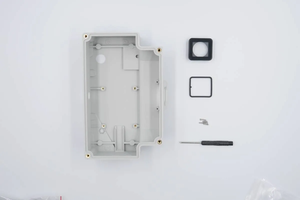
Prepare:

  • 1x main electronics box (3D-printed)
  • 1x camera shield
  • 1x camera shield gasket
  • 4x self-tapping torx screw (smallest in the kit)
  • T5x40 torx screwdriver
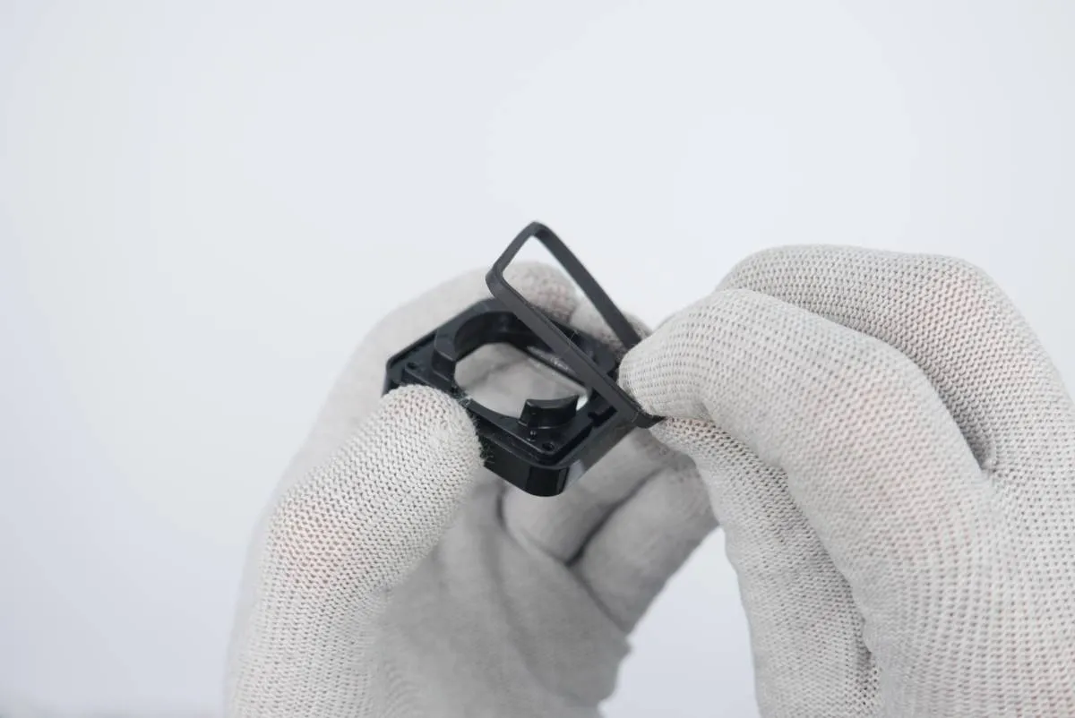
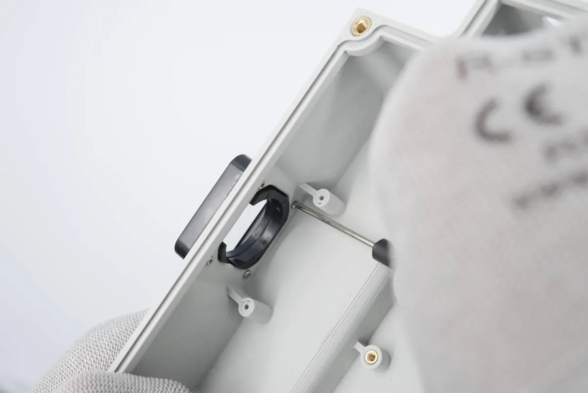
Put the camera shield gasket on the camera shield with a lip facing outwards.
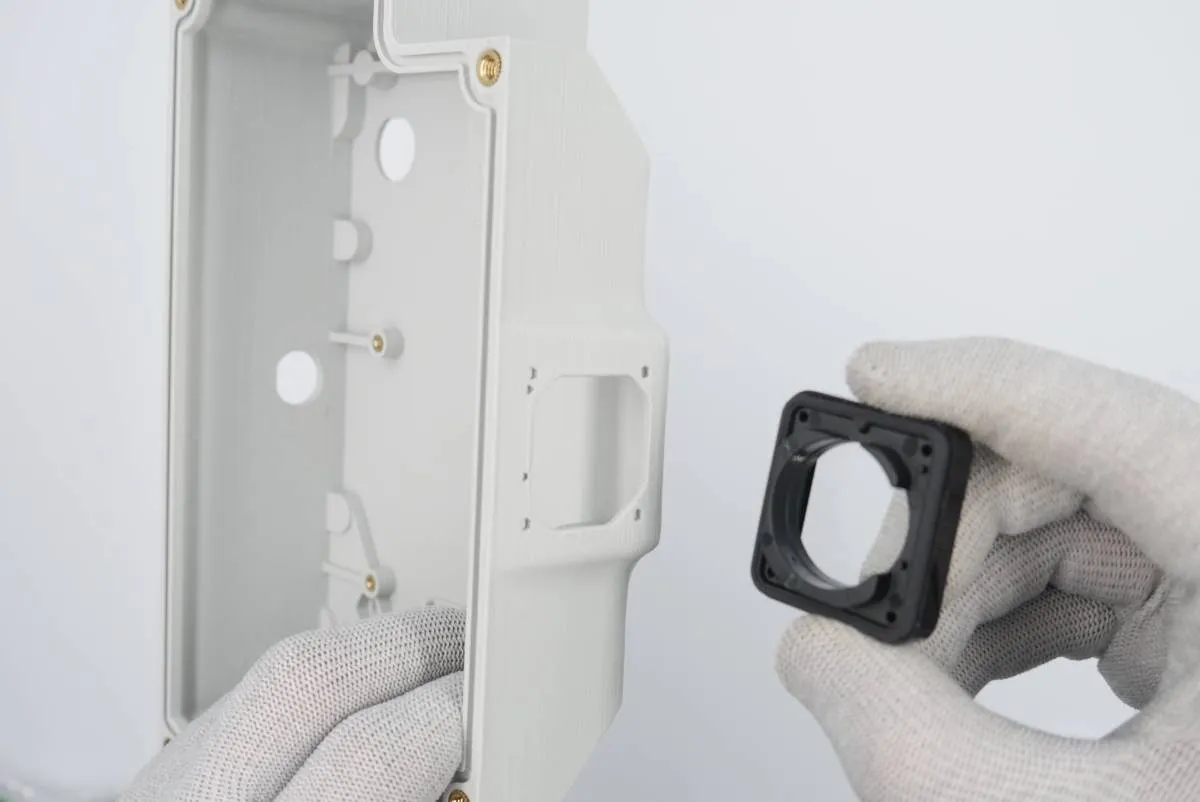
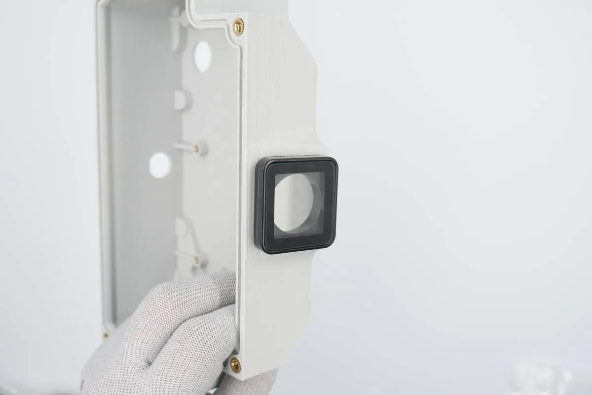
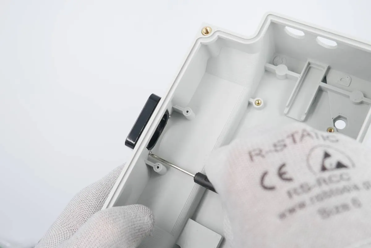
Secure the shield to the box using 4x self-tapping screws provided. This step needs a lot of patience.

Step 2: miniUSB and power cable

Prepare:

  • step 2 assembly
  • 1x power cable (3pin socket with barrel plug and green cable soldered)
  • 1x miniUSB socket with USB-A connector
  • 1x (optional) miniUSB socket cap (blue)
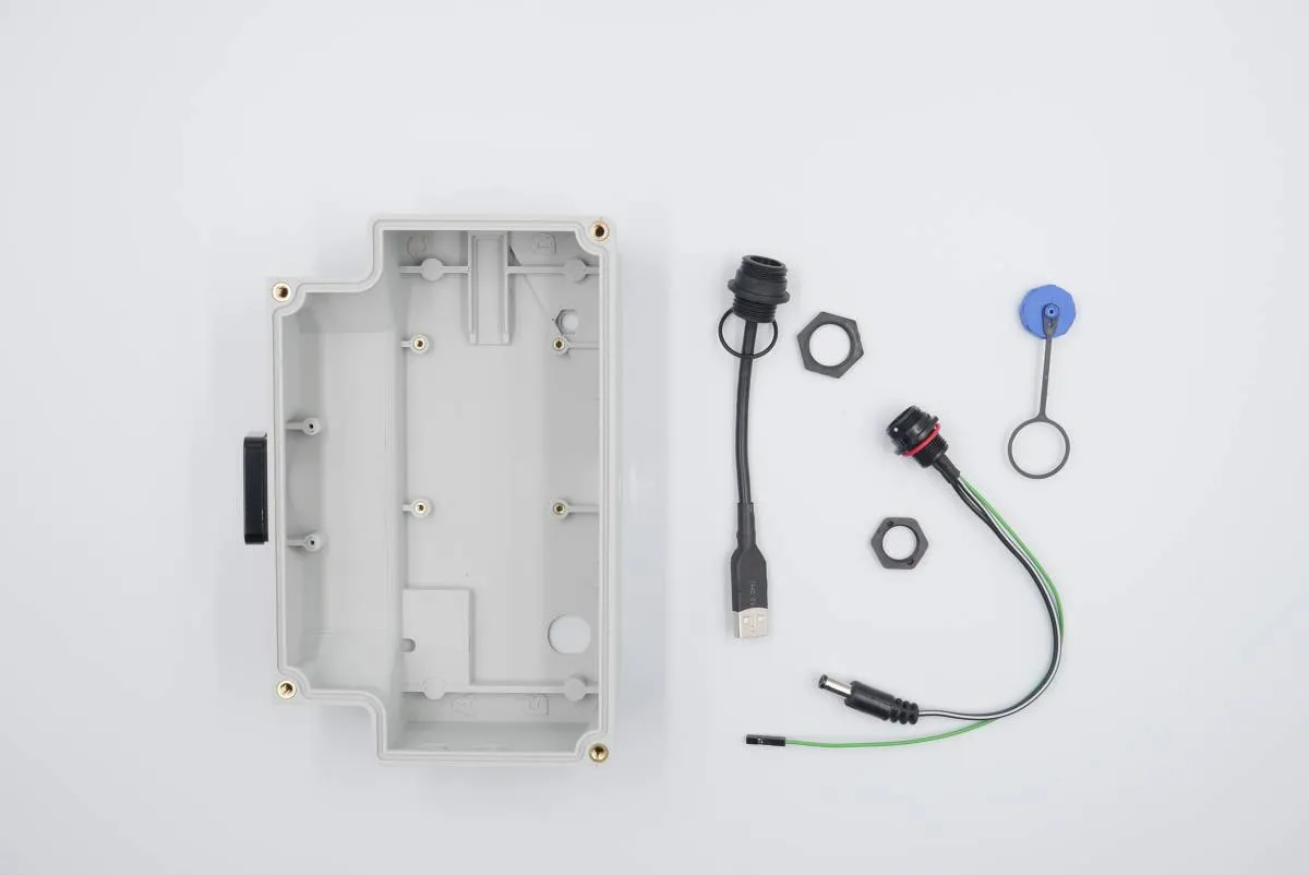
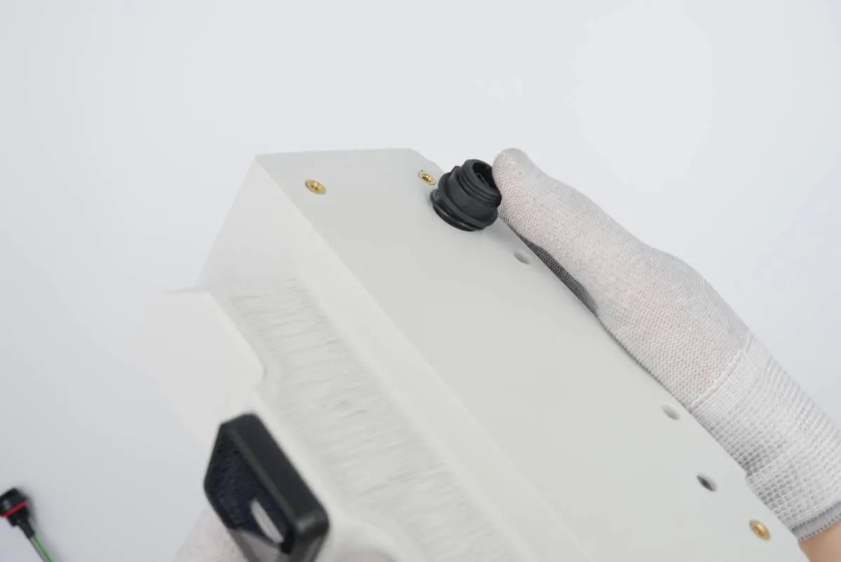
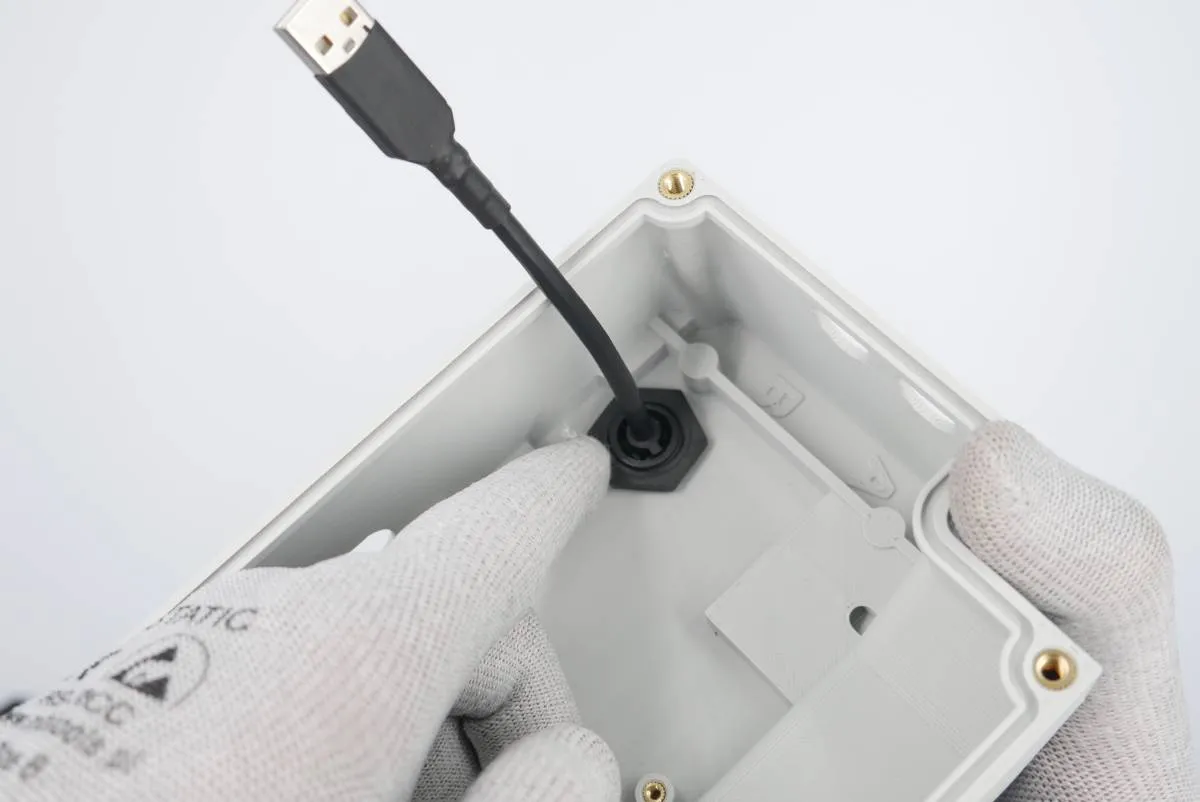
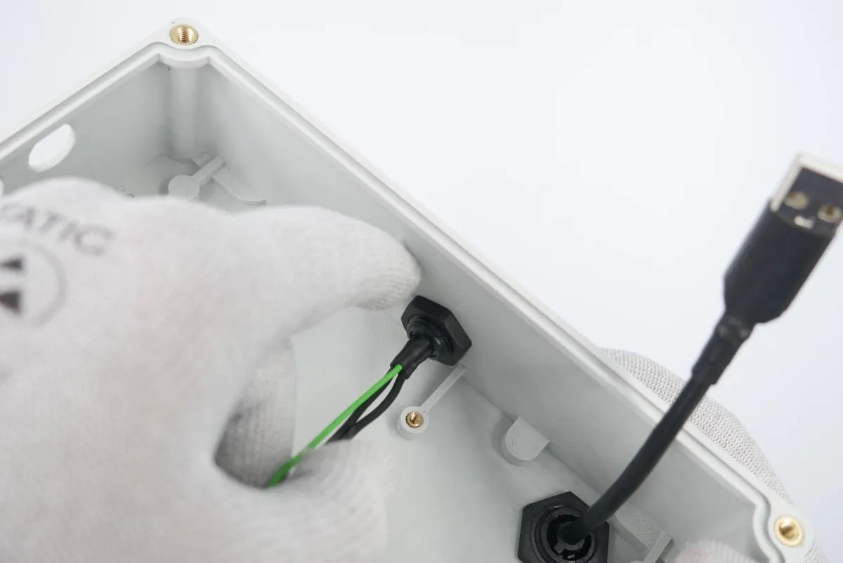
Insert the miniUSB socket into the opening in the main electronics box floor. Make sure the socket o-ring sits evenly.
Secure the socket using a plastic nut provided. Screw the nut by pressing the socket and using your fingers only.
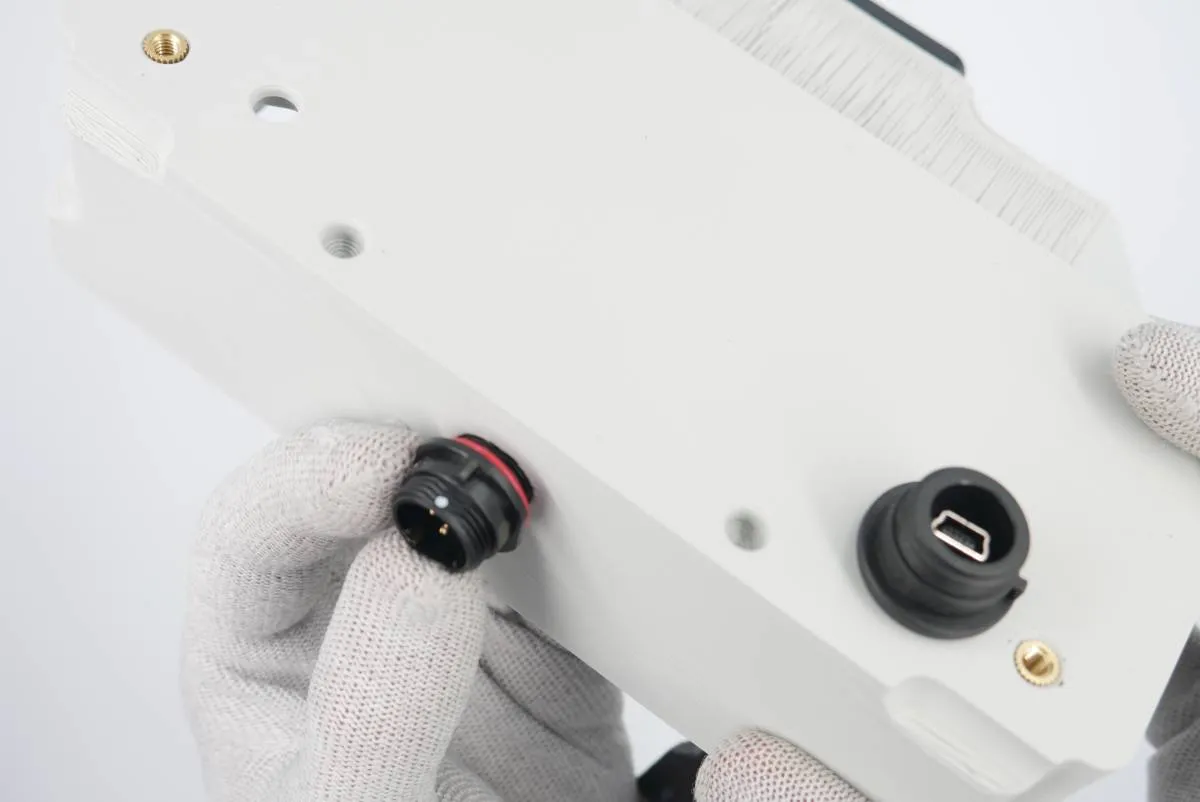
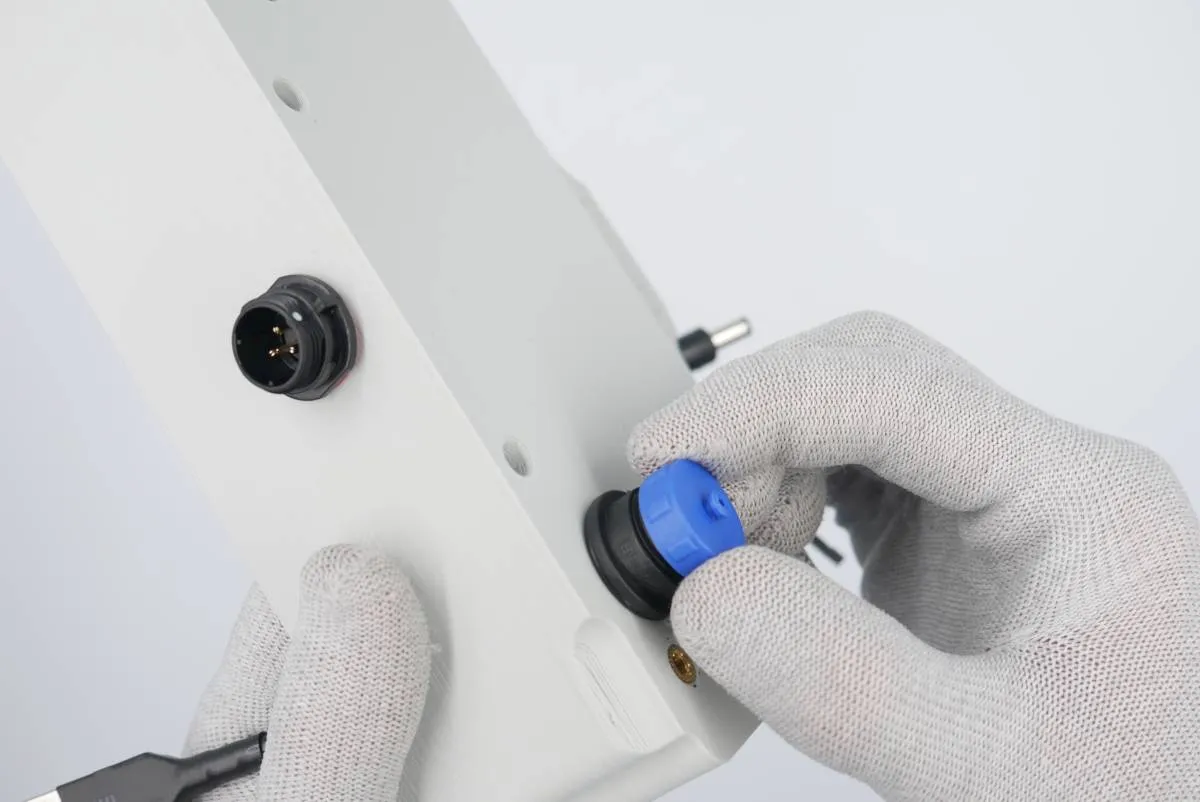
Insert the power socket into the hole in the rear of the main electronics box. Make sure the socket o-ring sits evenly.
Secure the socket using a plastic nut provided. Screw by pressing the socket and using your fingers only.
(optionally) Attach the miniUSB socket cap.

Step 3: Antenna cable

Prepare:

  • step 2 assembly
  • 1x antenna cable, a nut and toothed washer
  • 1x small o-ring
  • vaseline (optional)
  • 8mm flat wrench
warning

Don't use the spring washer that may be provided with the antenna cable. Use only the toothed washer.
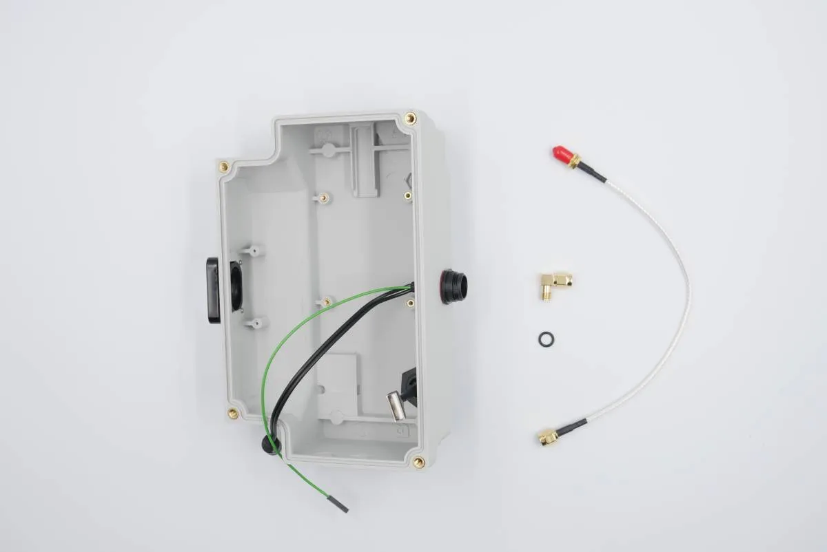
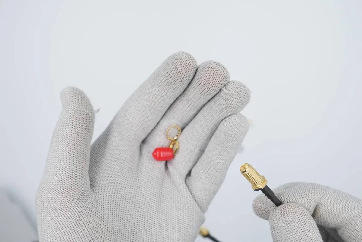
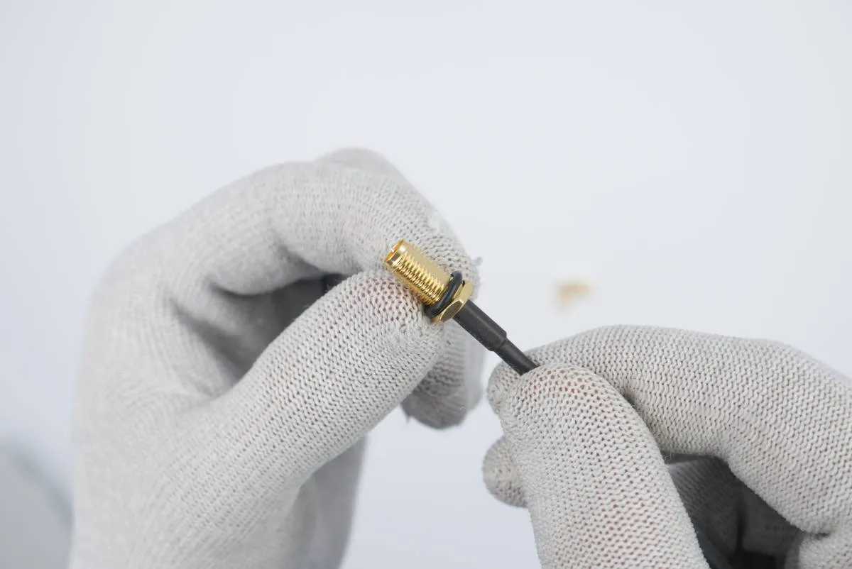
Detach the toothed washer, the nut and the cap from the antenna cable.
Put the small o-ring on the antenna cable socket. (optionally) Smear some vaseline on the o-ring.
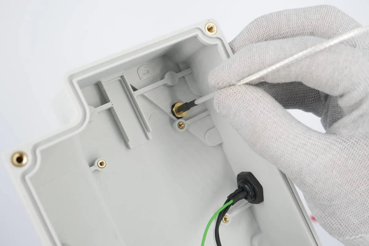
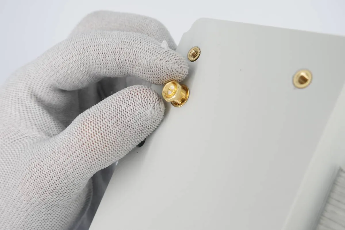
Press the antenna cable socket to the hex-shaped opening in the main electronics box floor.
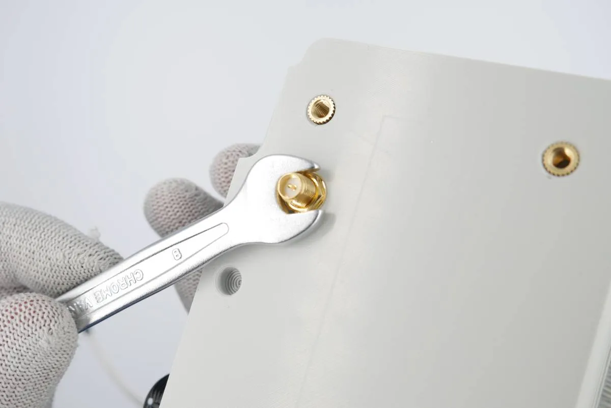
On the other side of the box - put the toothed washer and the nut on the socket.
Tighten the washer using the 8mm wrench provided. Tighten with no excessive force.
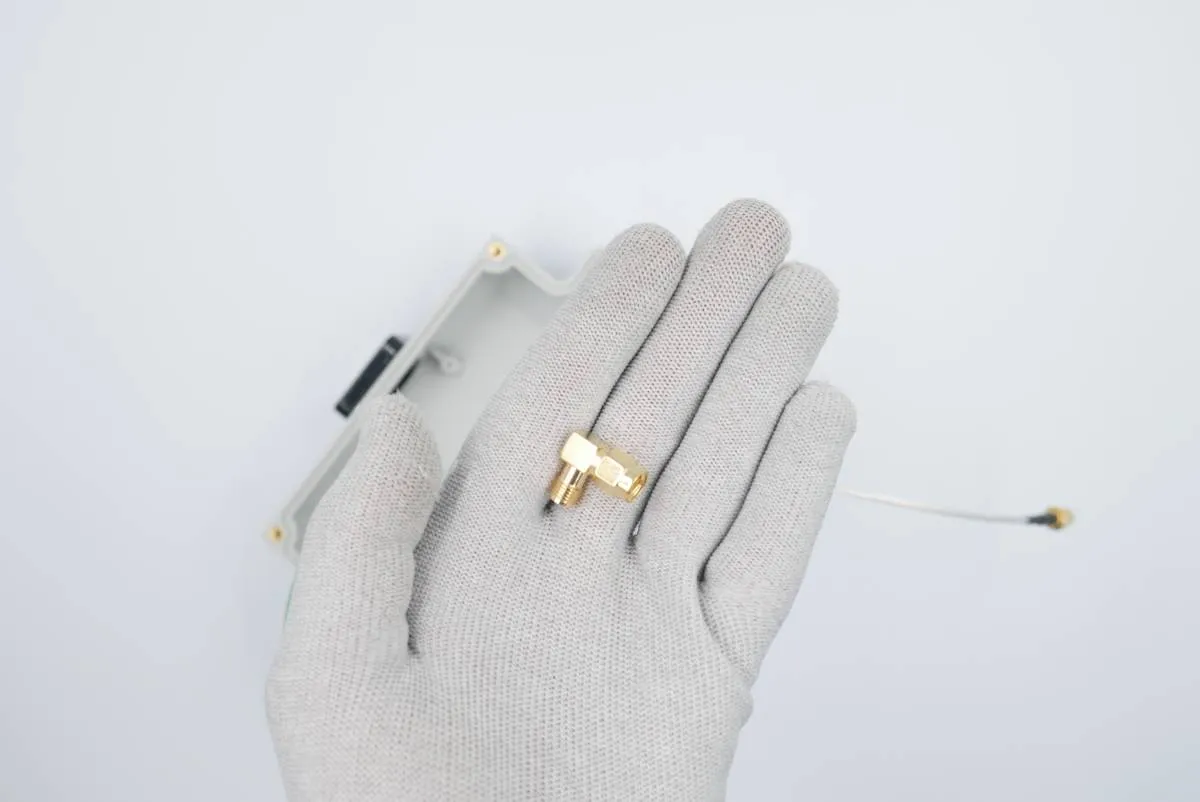
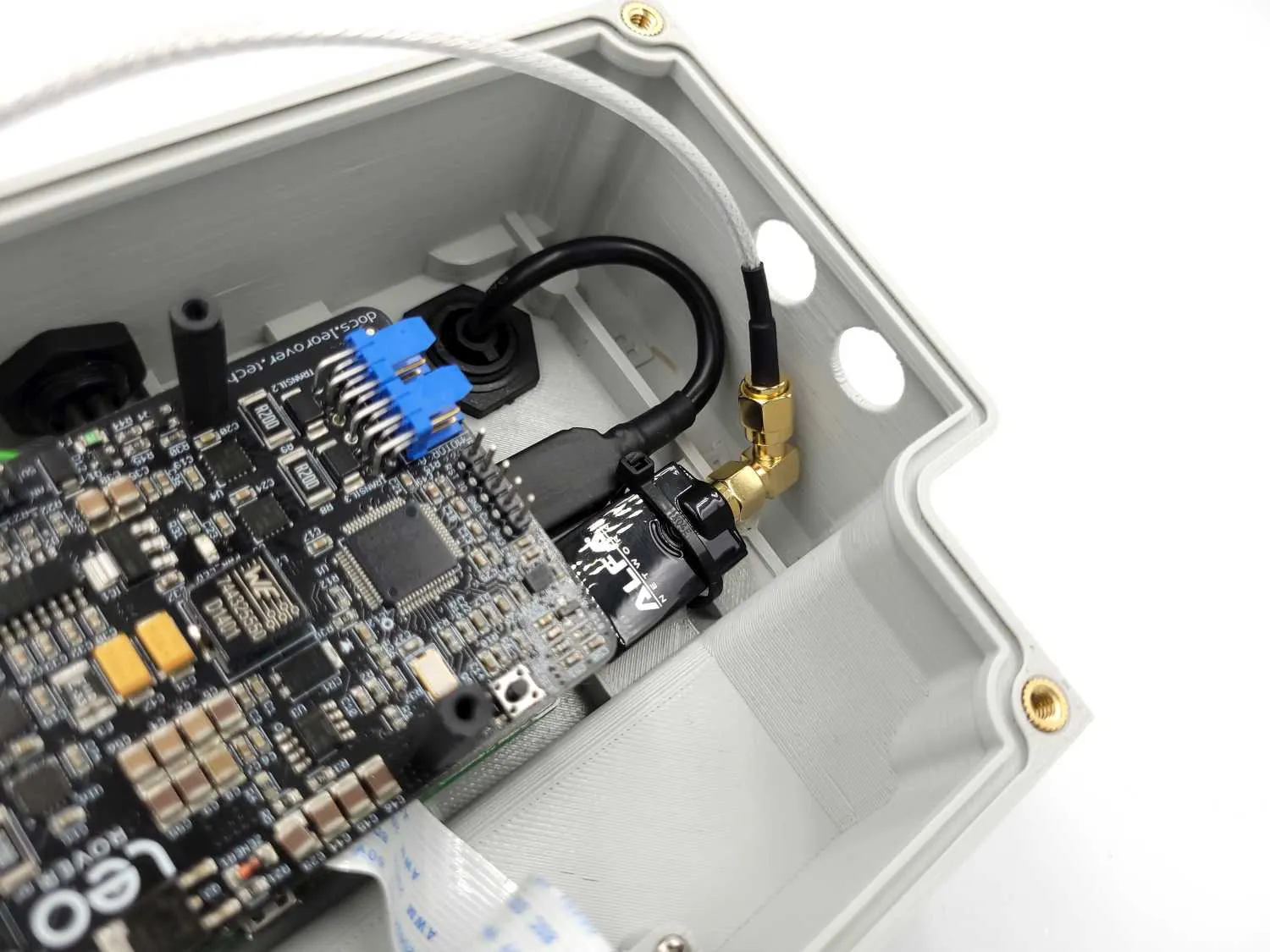
After the step you'll end up with a 90deg. adapter that will be used in step 5 of the assembly.

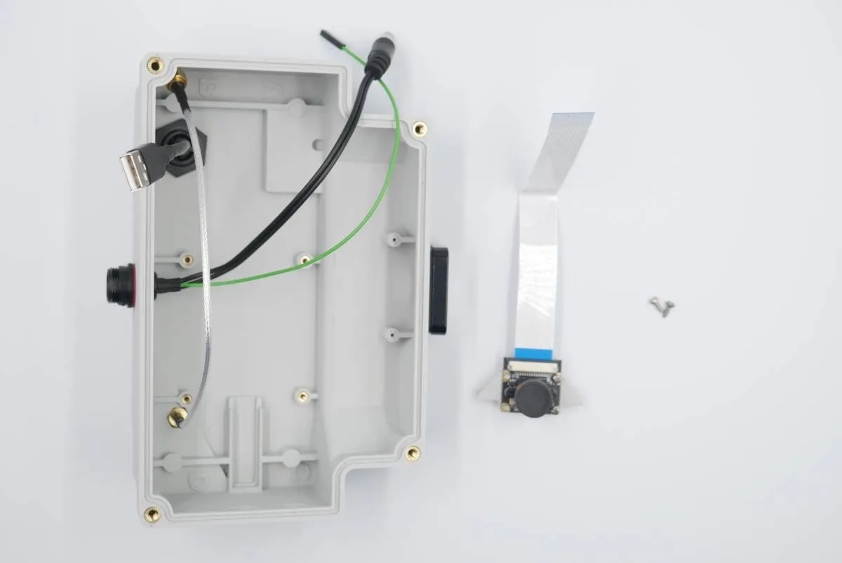
Step 4: Camera

Prepare:

  • step 3 assembly
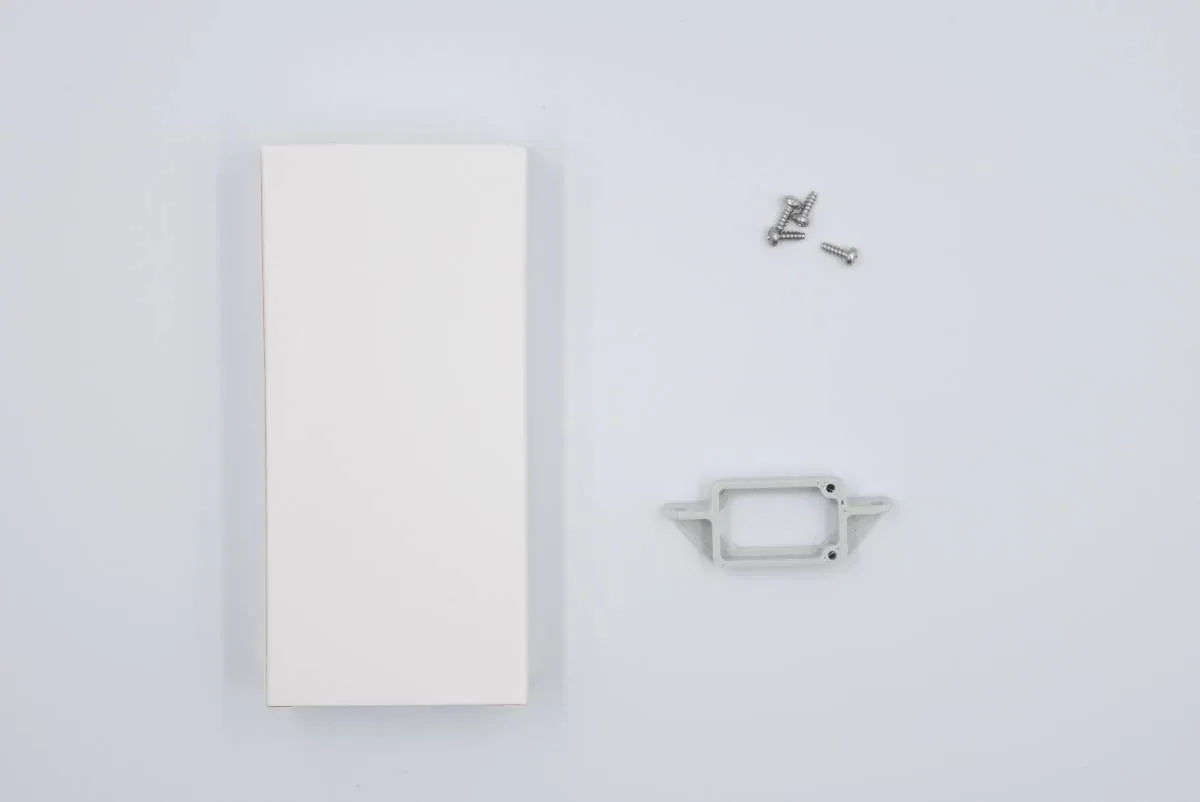
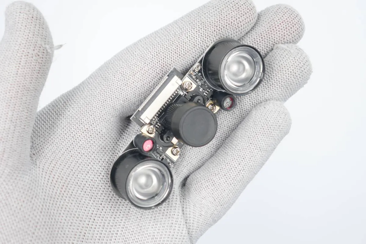
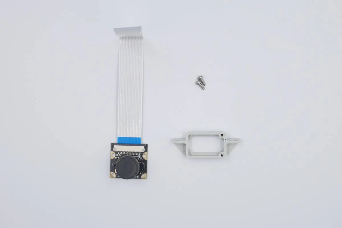
  • 1x fisheye camera (white box)
  • 1x plastic camera mount (3D-printed)
  • 4x 2.2x6.5 self-tapping screws (cross-headed)
  • cross-head screwdriver
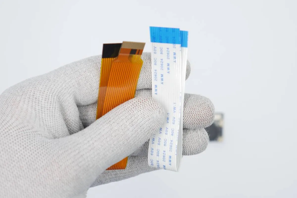
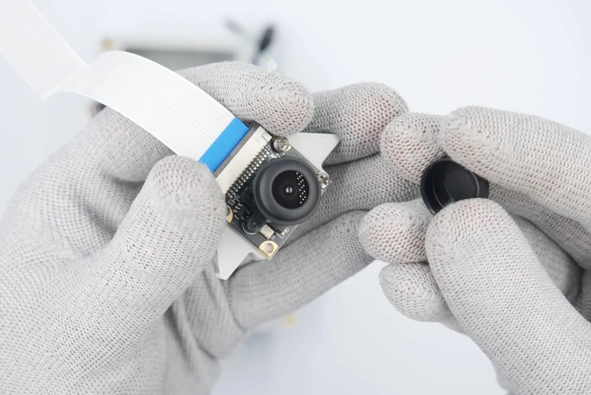
Open the white box (with the camera and the camera connection tapes).
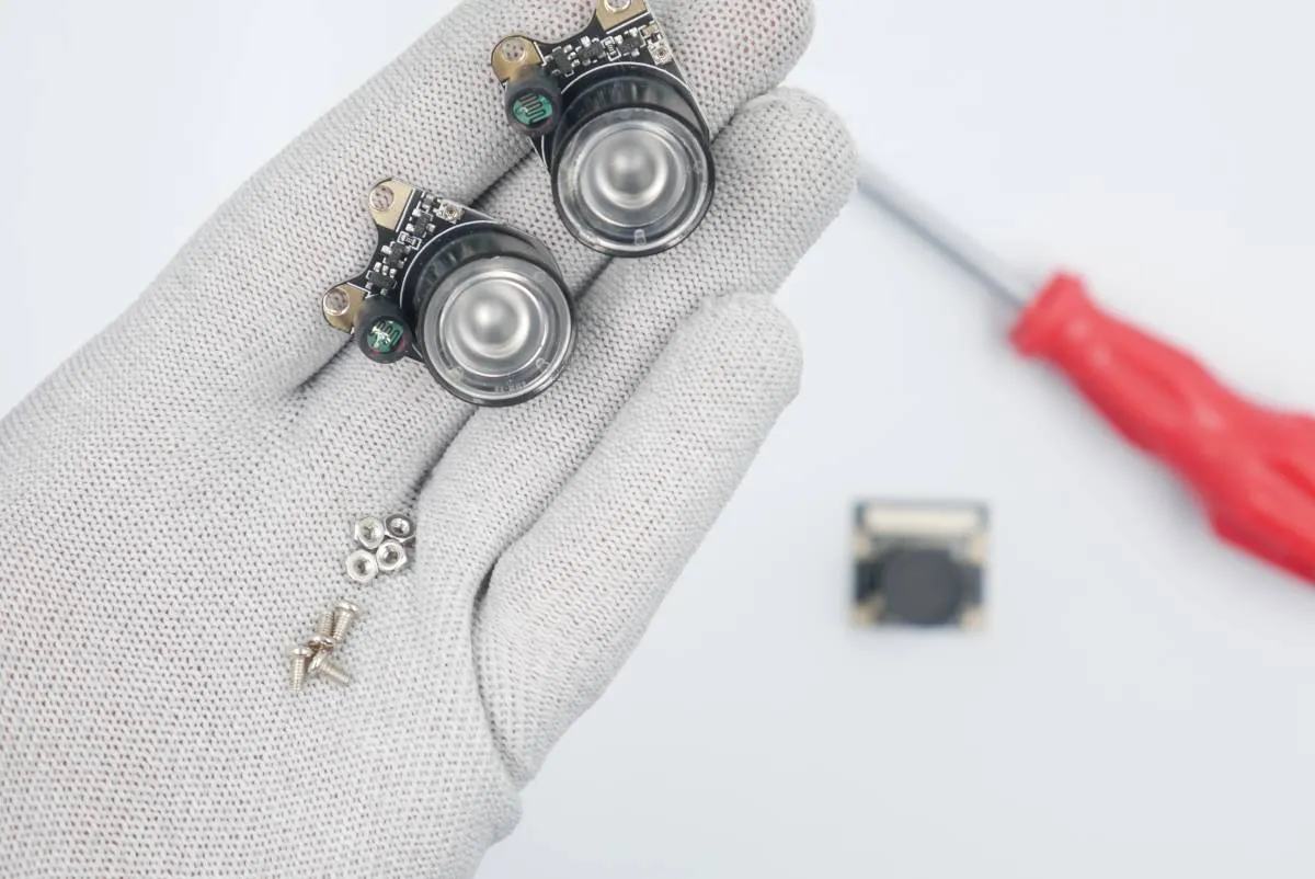
Detach the IR lights that come assembled to the camera module. Store them somewhere as they won't be used in the assembly process, but may become handy in other projects.
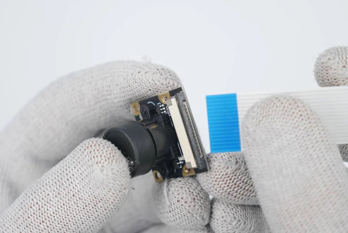
Use the white-blue tape, toss away or store the second one (dedicated only to RaspberryPi Zero that we don't use here).
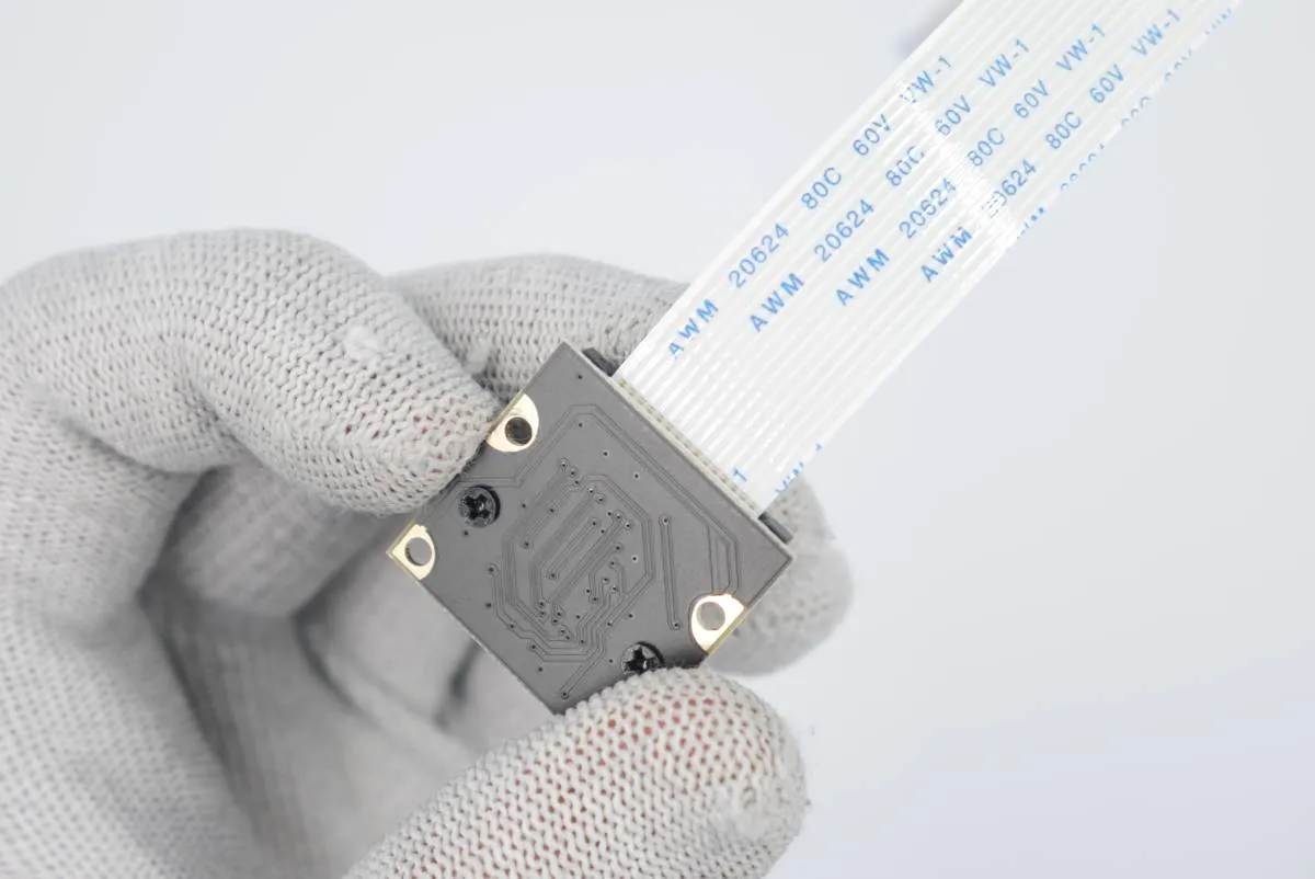
Connect the tape to the camera module. Make sure the tape connection surfaces meet the camera metal pins in the socket.
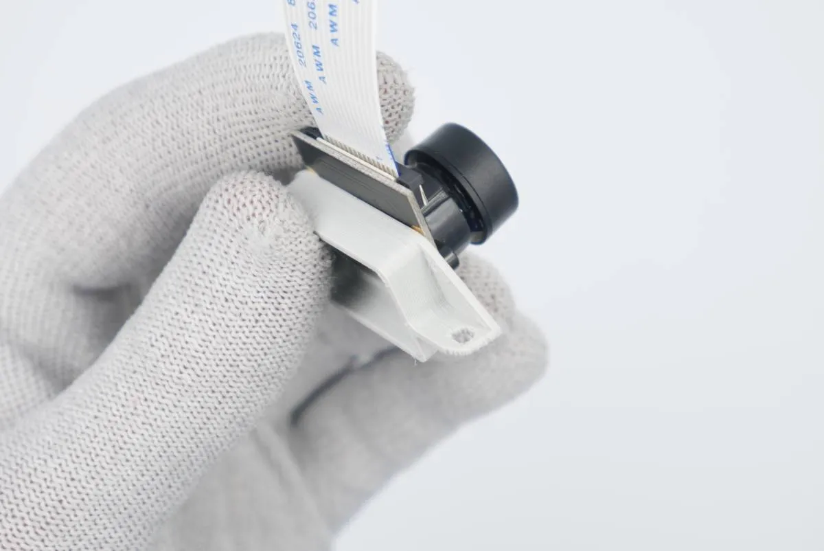
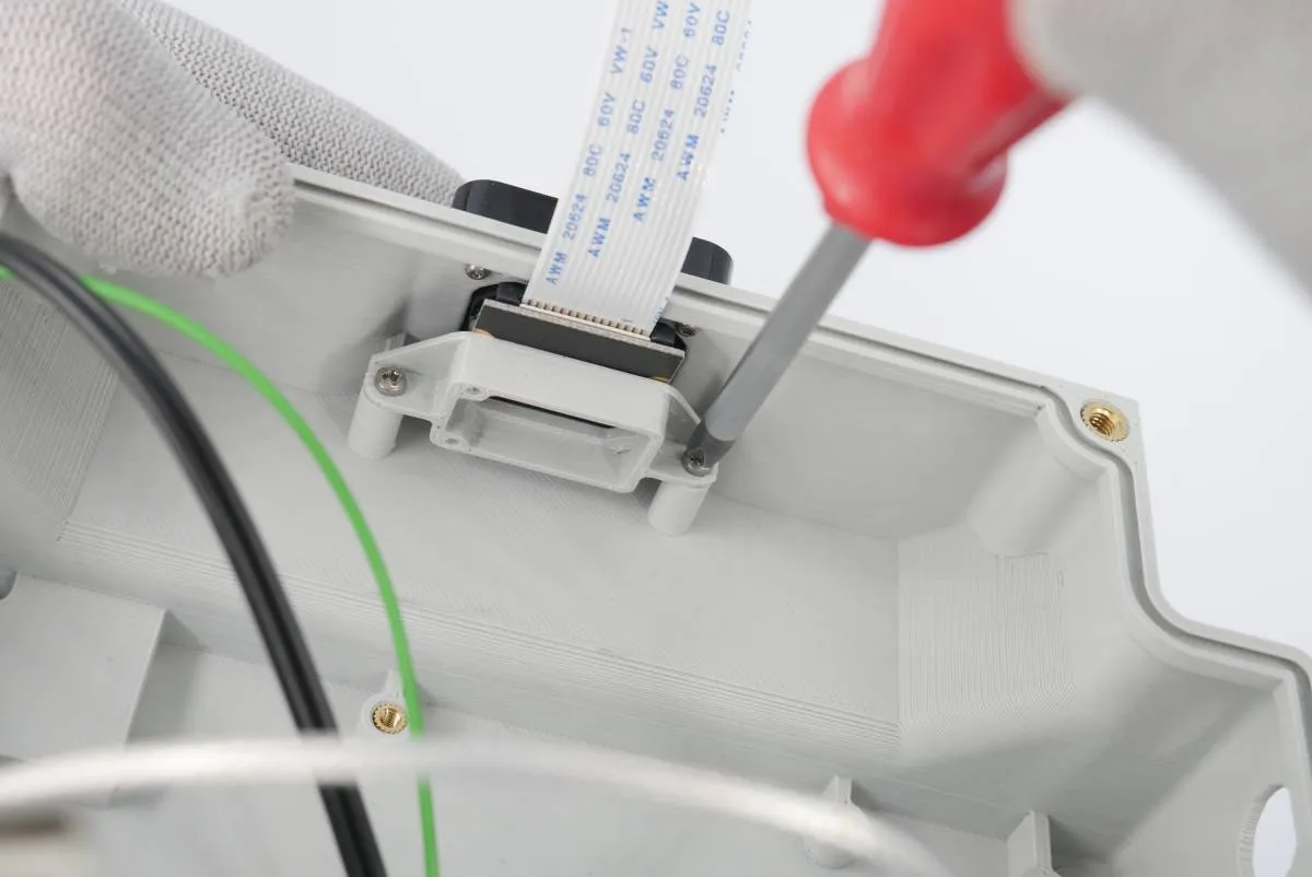
Combine the camera module with the 3D-printed camera mount as in the photo.
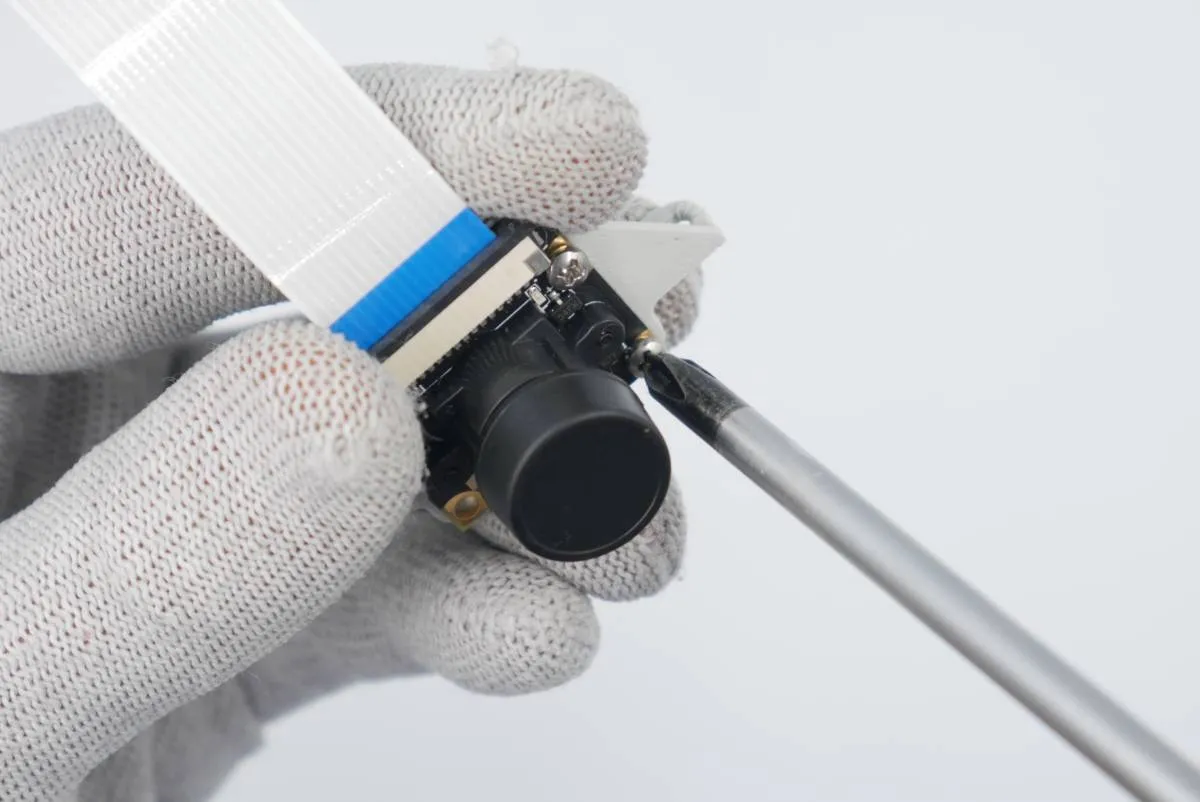
Screw the pair together using 2x 2.2x6/5 self-tapping screws.
Detach the plastic cover from the camera lens.
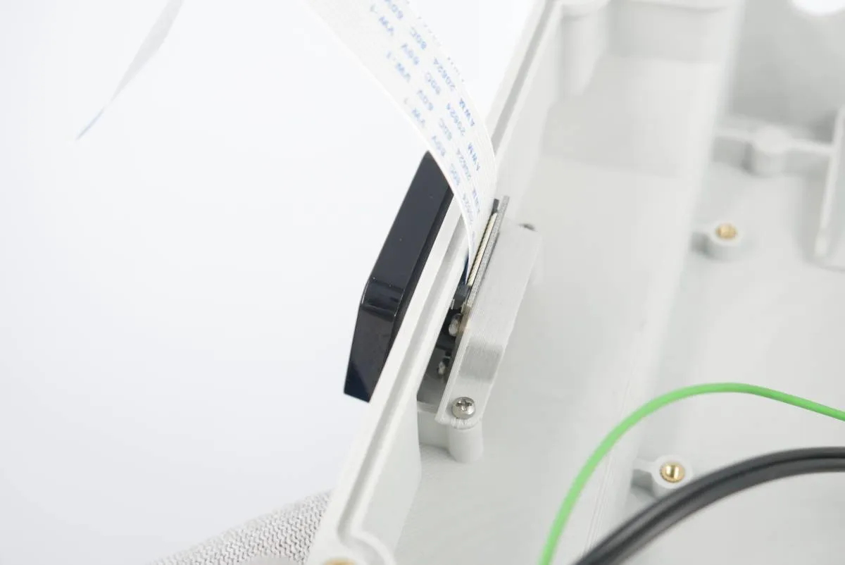
Attach the camera assembly to the main electronics box camera housing. Screw them together using remaining 2x 2.2x6.5 self-tapping screws. Be gentle with the force as the thread may be easily broken.

Step 5: RaspberryPi and WiFi modem assembly

Prepare:

  • step 4 assembly
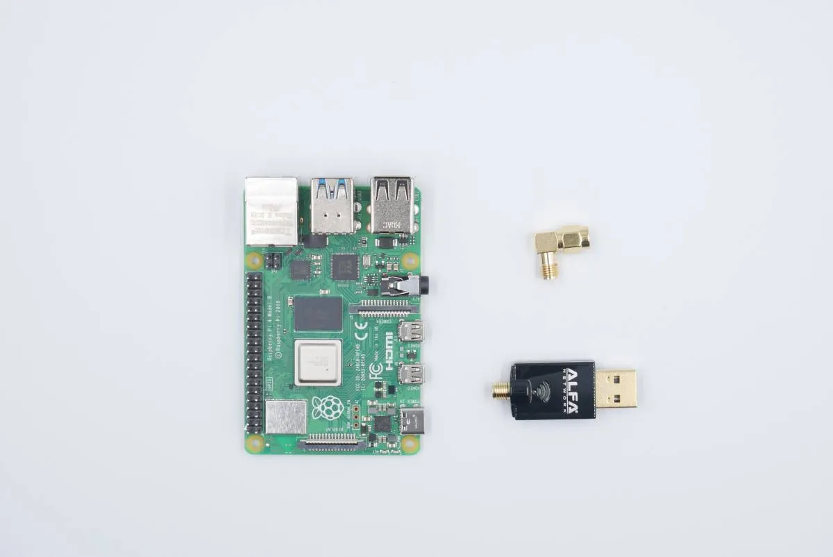
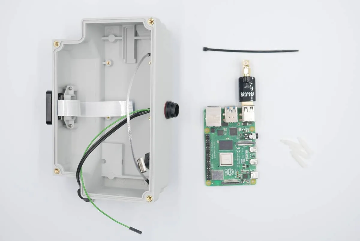
  • 1x RaspberryPi board
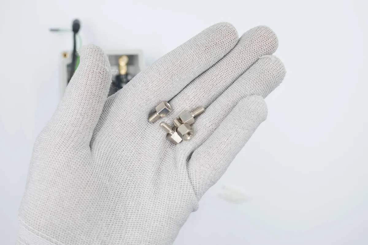
  • 4x m2.5x18 plastic distances
  • 4x m4x6 metal distances
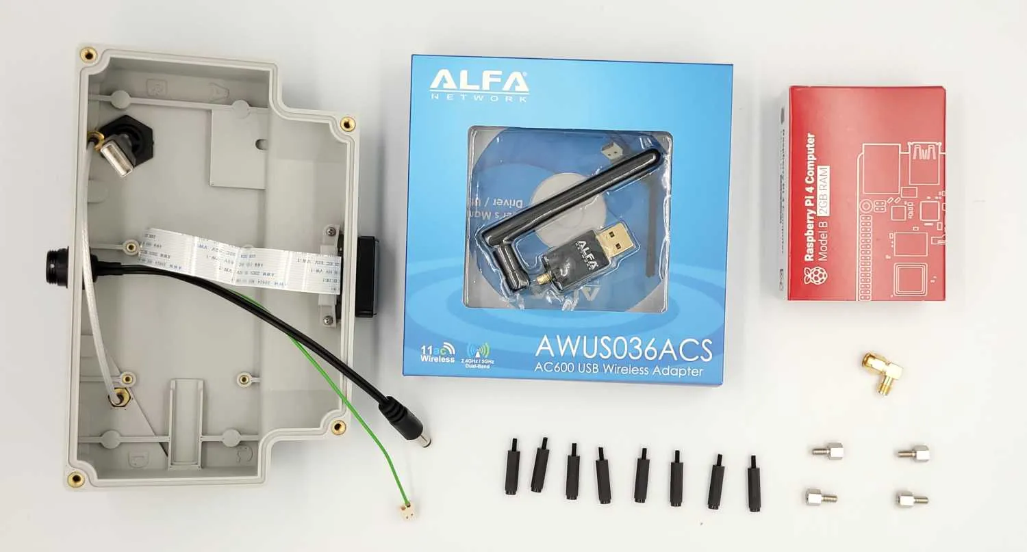
  • 1x ALFA USB WiFi modem
  • 1x 90deg antenna adapter (from previous steps)
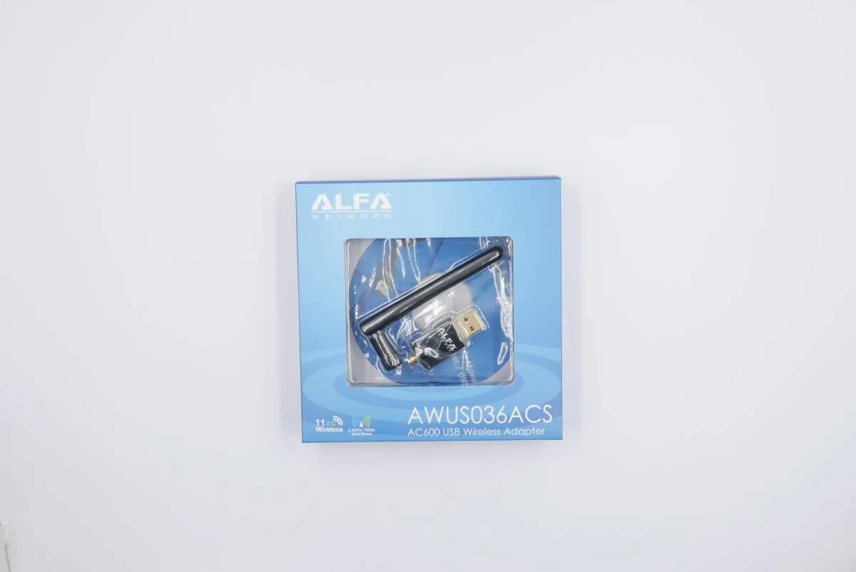
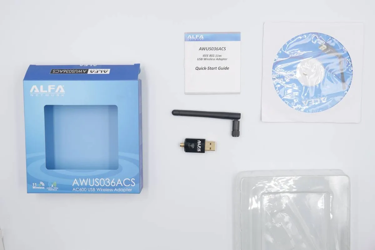
Take the ALFA modem box and open it.
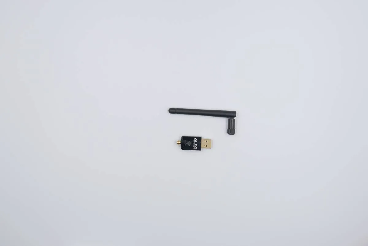
Leave only the modem and the antenna. Everything else is not needed.
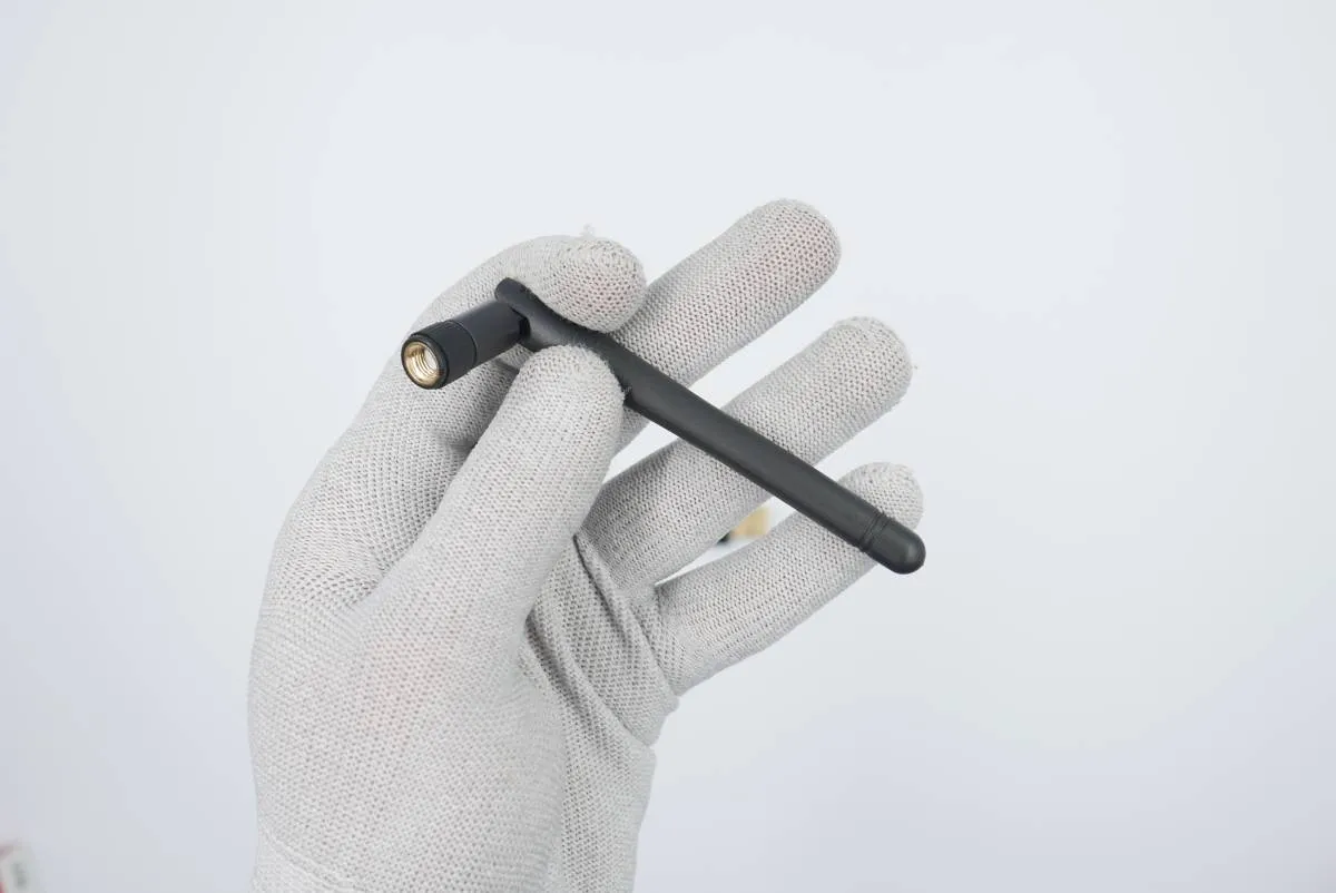
Store the antenna as it will be needed in Task 8 of the assembly.
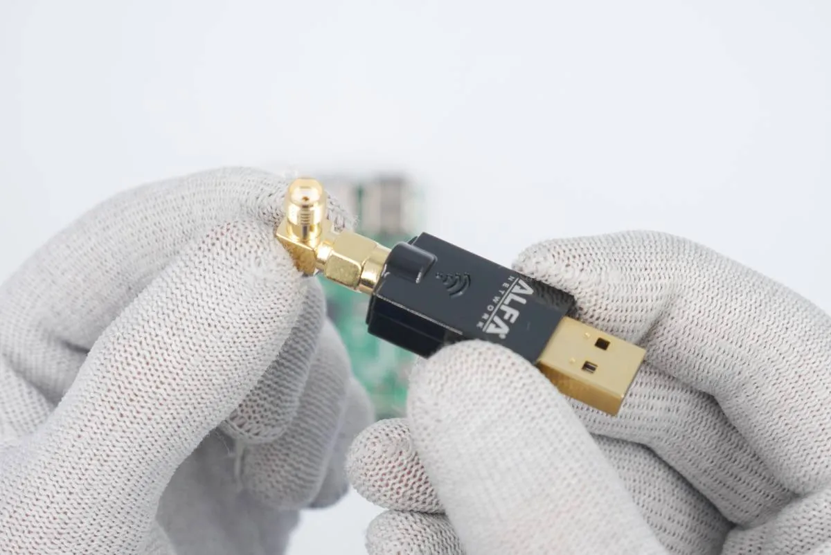
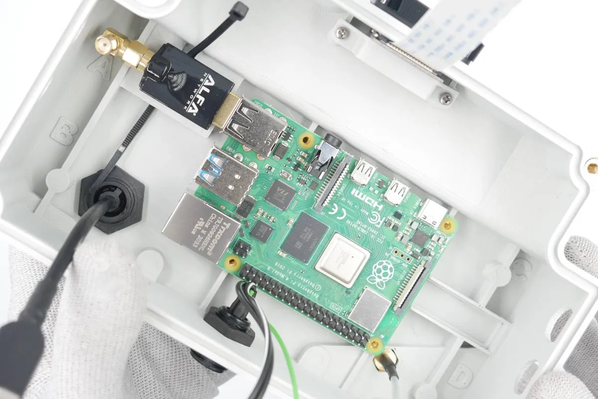
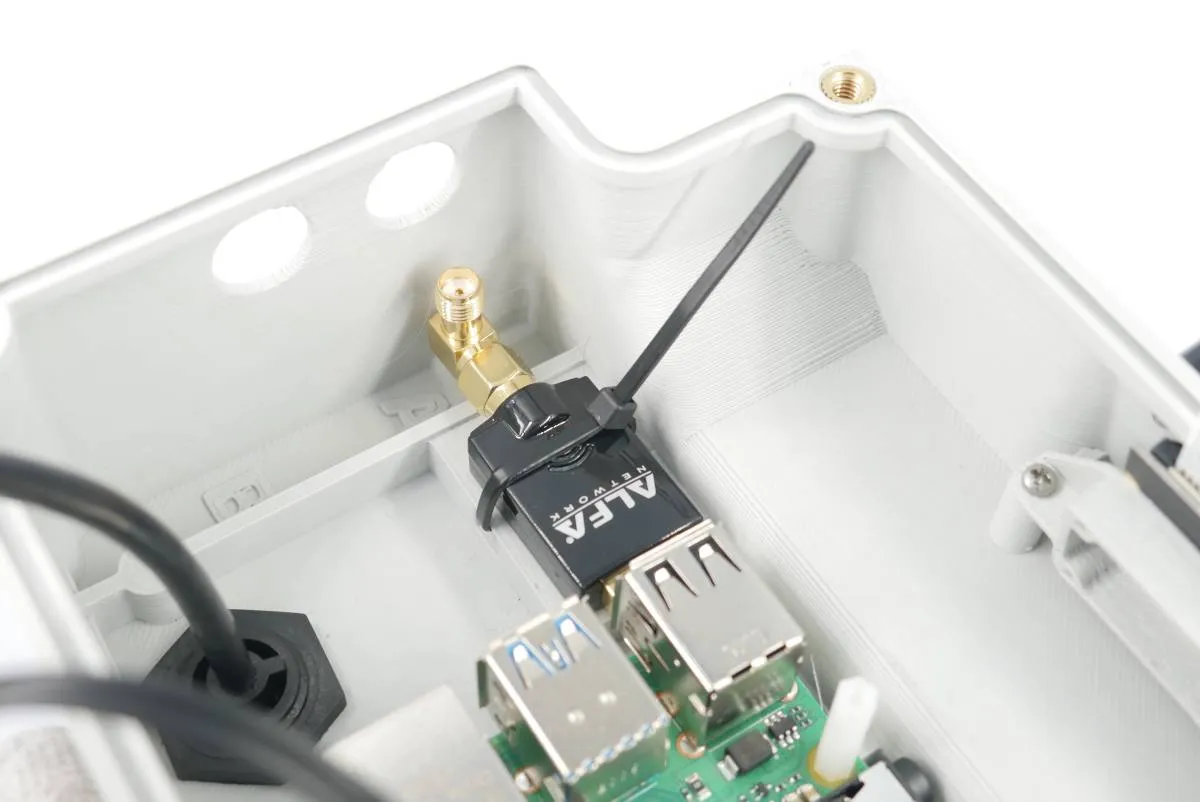
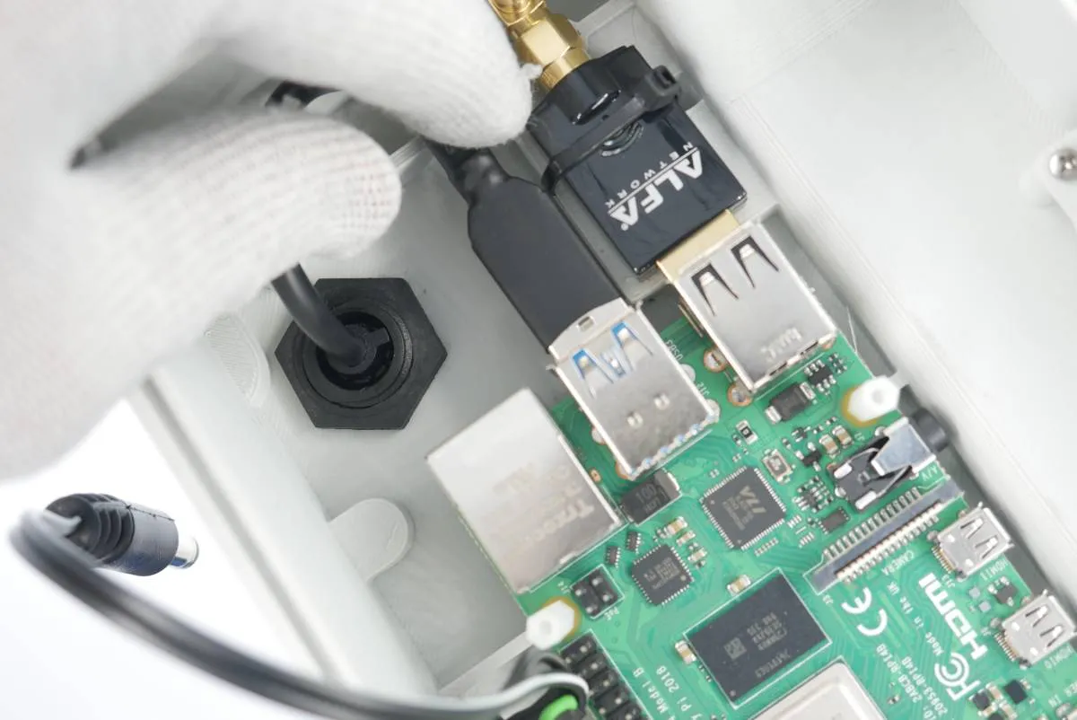
Connect the 90deg antenna adapter to the WiFi modem.
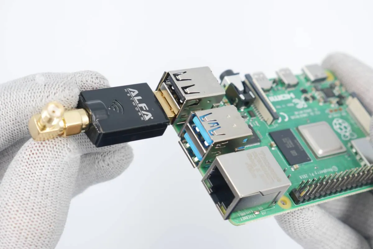
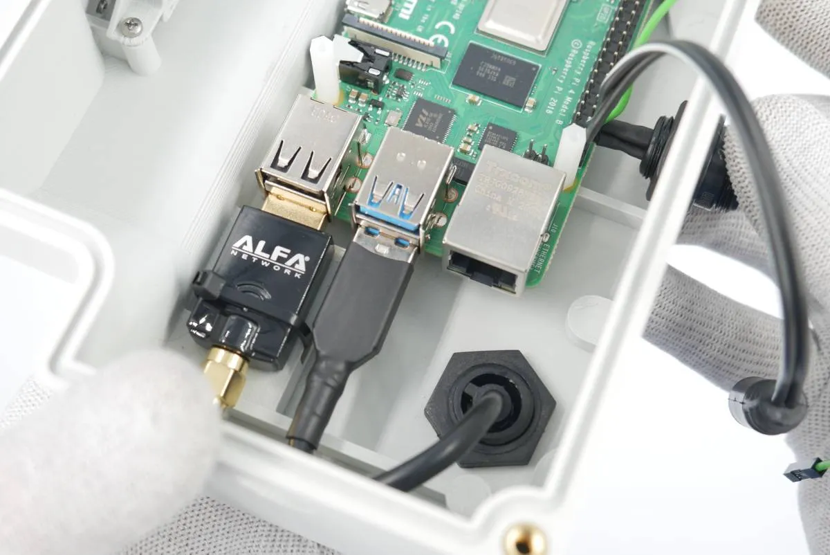
Connect the modem to the lower left USB port of the RaspberryPi.
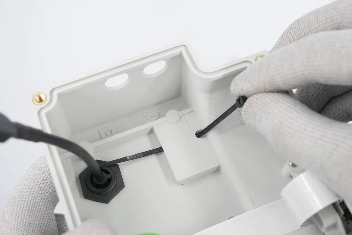
Thread one zip-tie through a tunnel in the modem support (main electronics box floor).
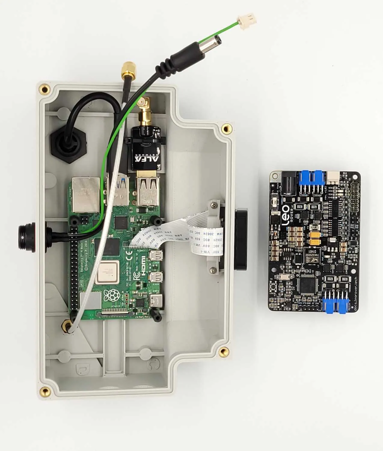
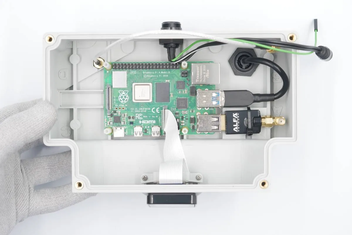
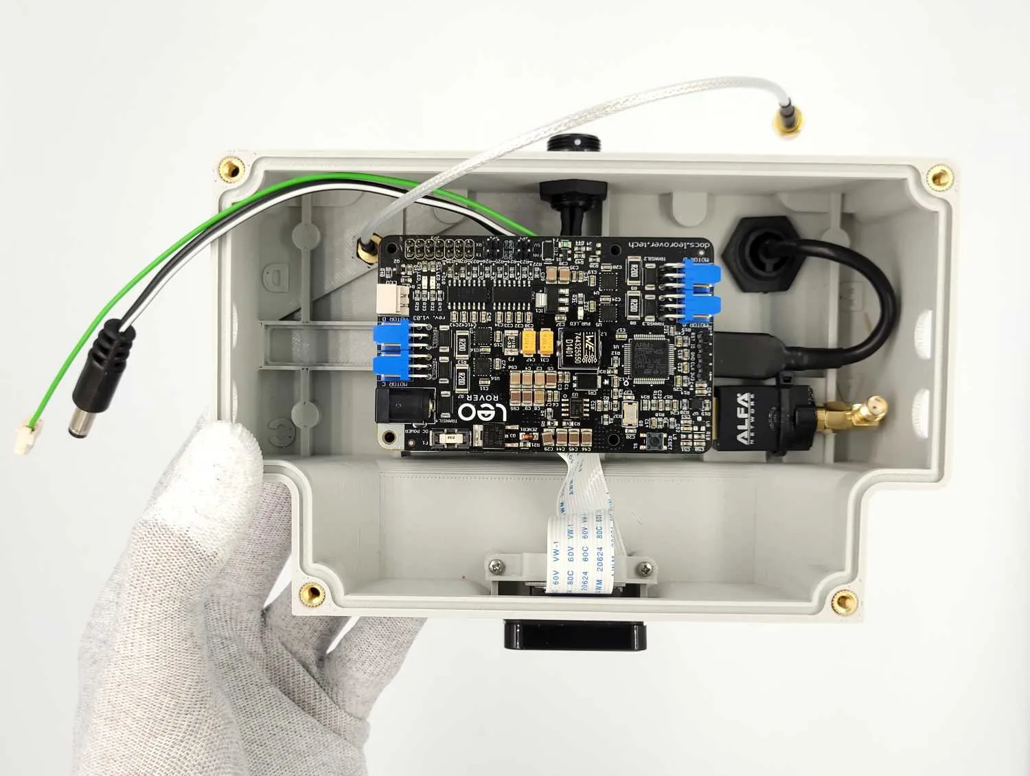
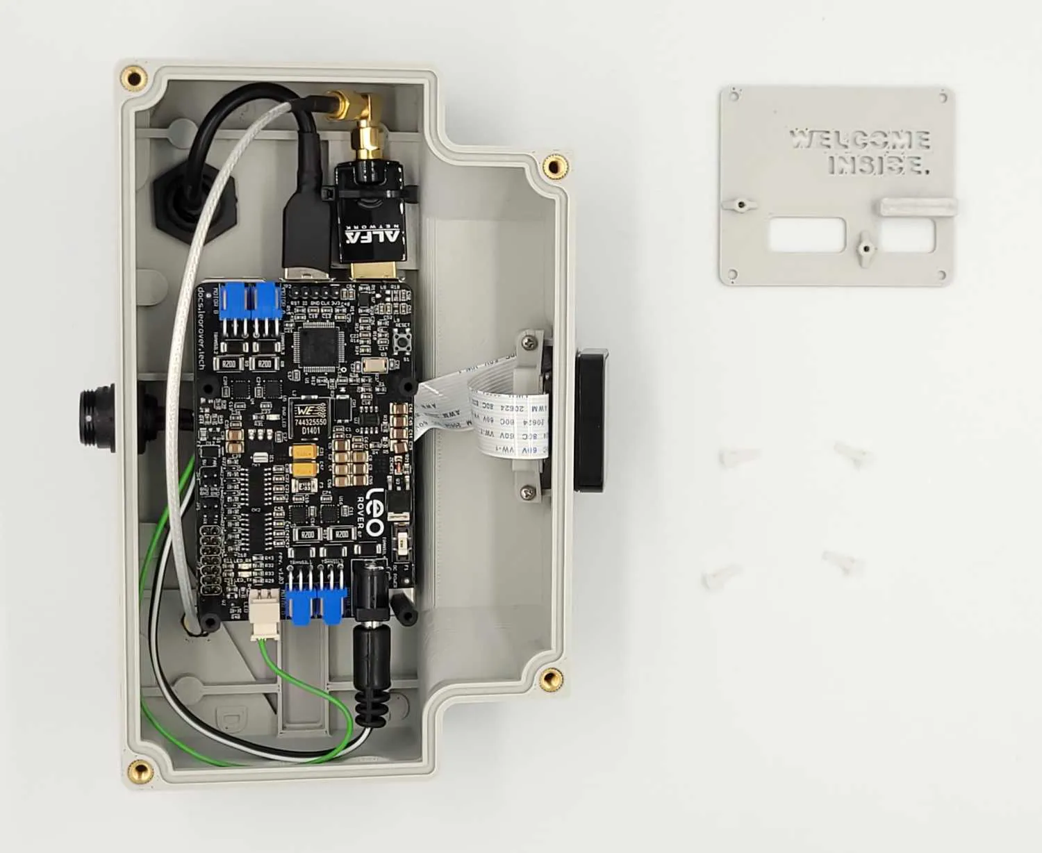
Align the RaspberryPi and WiFi modem assembly as in the photo.
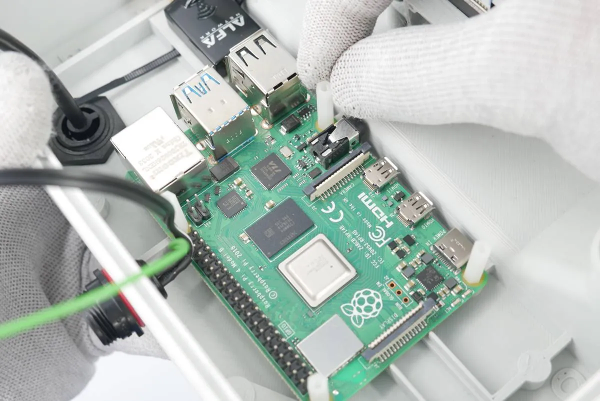
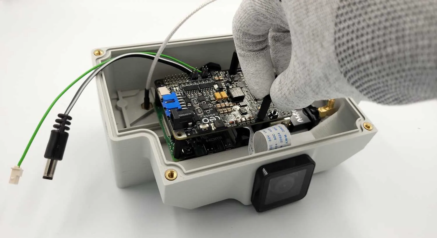
Secure the board to the main electronics board using 4x plastic distances.
Tie the zip-tie securing the WiFi modem in place and cut the excess.
Roll the miniUSB socket cable as in the photo and connect its USB socket to the rear port of the RaspberryPi board.
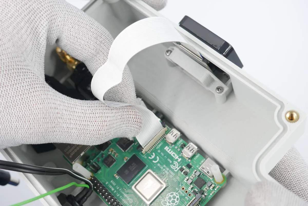
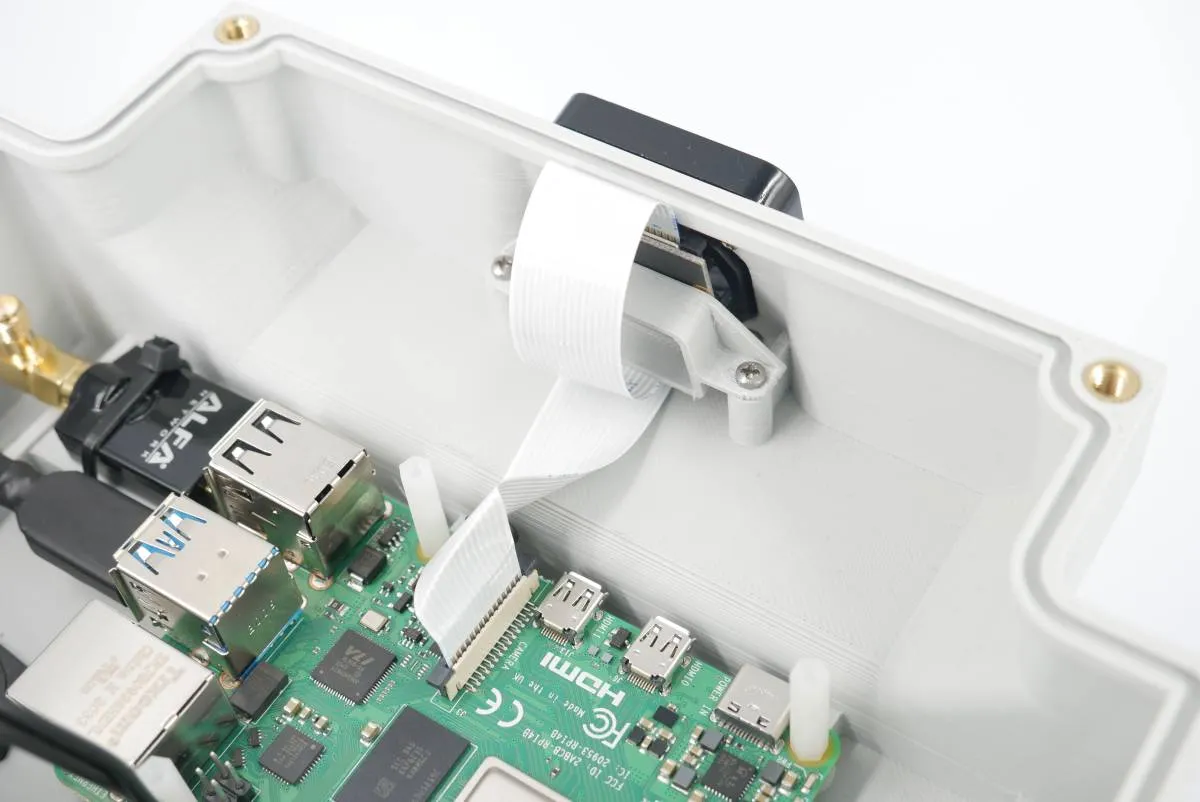
Connect the camera tape to CAMERA port of the RaspberryPi. Remember that the socket pins must match the tape connectors.
Roll the tape under the camera housing to give space for other components.
After the step you'll end up with 4 metal distances that will be used later in the assembly task.

Step 6: Controller assembly and cabling

Prepare:

  • step 5 assembly
  • 1x controller electronics board (LeoCore/Husarion Core2-ROS)
  • 4x m2.5x18 plastic distance
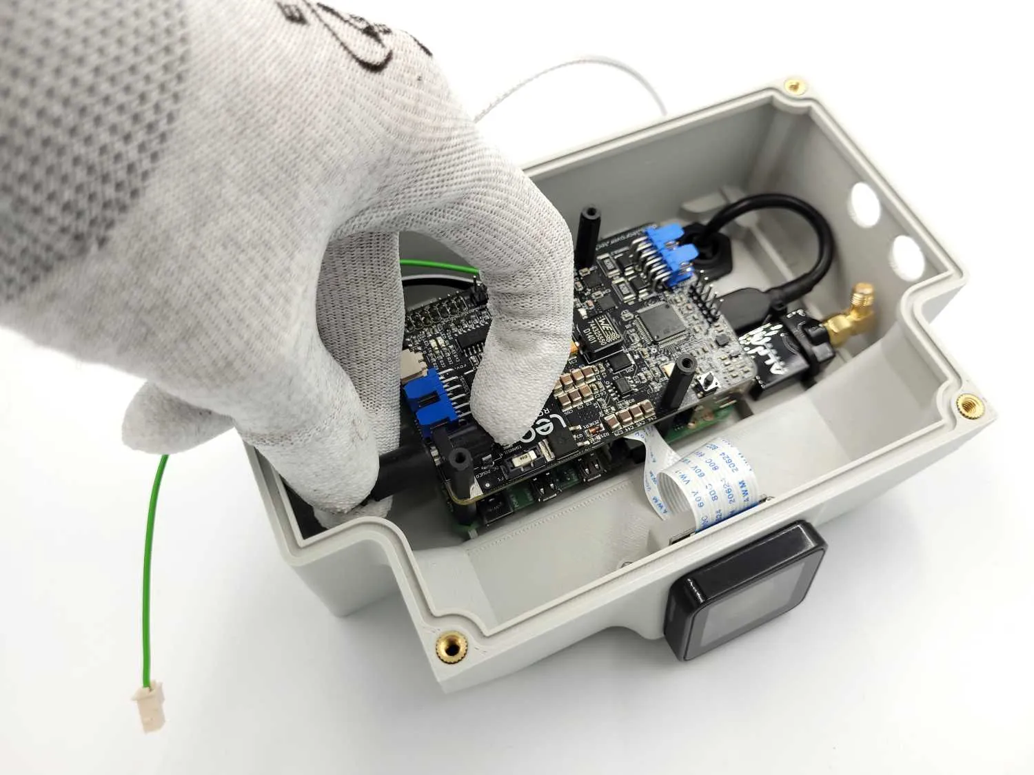
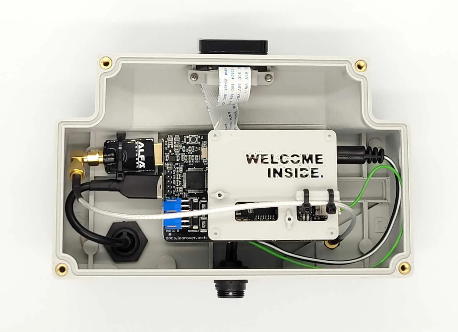
Insert the LeoCore board into the main electronics box and connect the rear socket to the RaspberryPi GPIO pins. Make sure the mounting holes of the controller are aligned with RaspberryPi's (and plastic distances) holes.
Secure the boards together using 4x plastic distances provided.
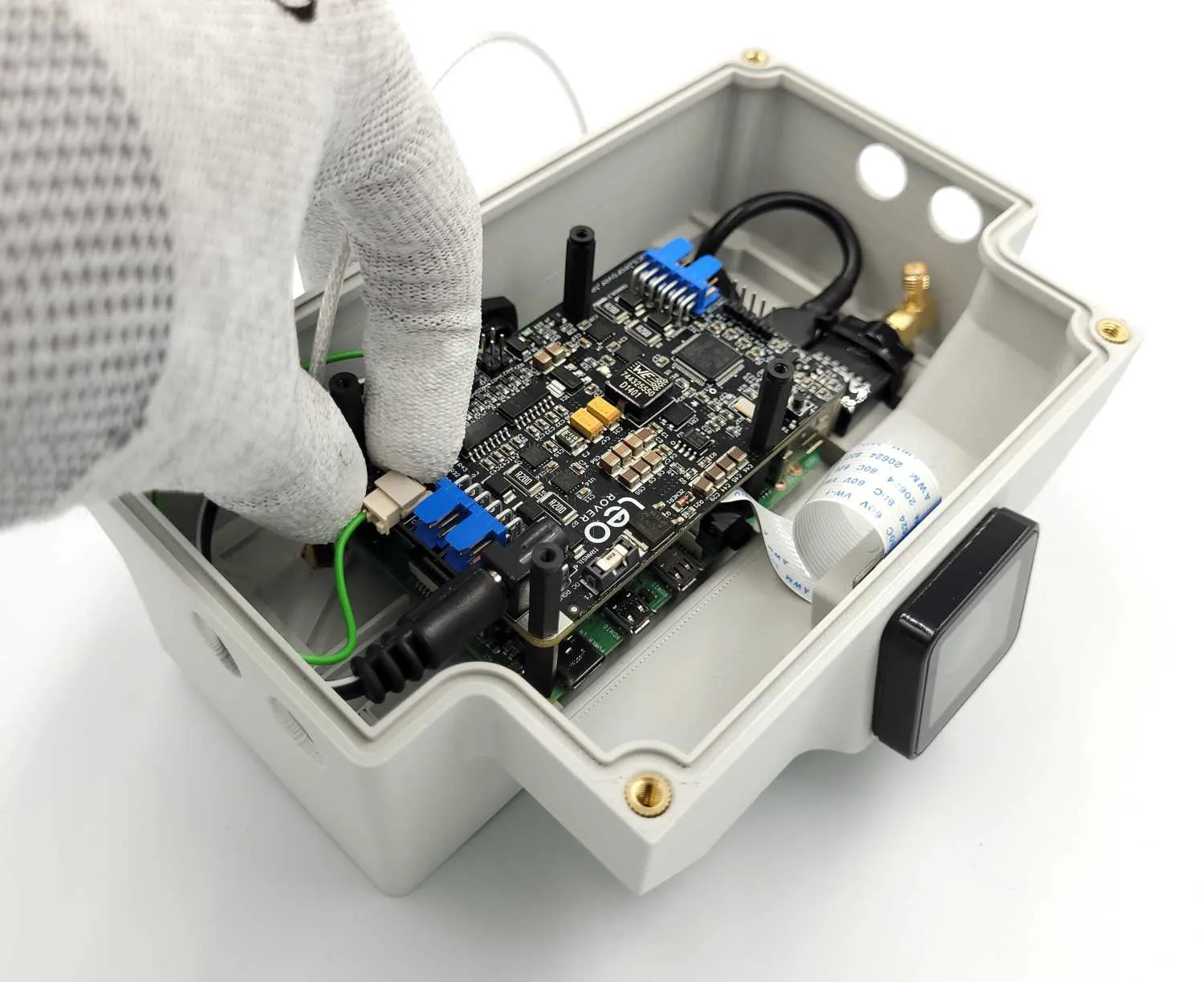
Connect the power cable barrel plug to the power socket of the LeoCore board.
Connect the power cable green wire to its socket as in the photo.
Connect the antenna cable to the 90deg antenna adapter that was previously assembled to the Wifi modem. There's little space there so you need to be gentle.

Step 7: Electronics cover

Prepare:

  • step 6 assembly
  • 1x electronics cover (3D-printed)
  • 2x small zip-ties
  • 4x m2.5 plastic screws
  • cross-head Philips screwdriver
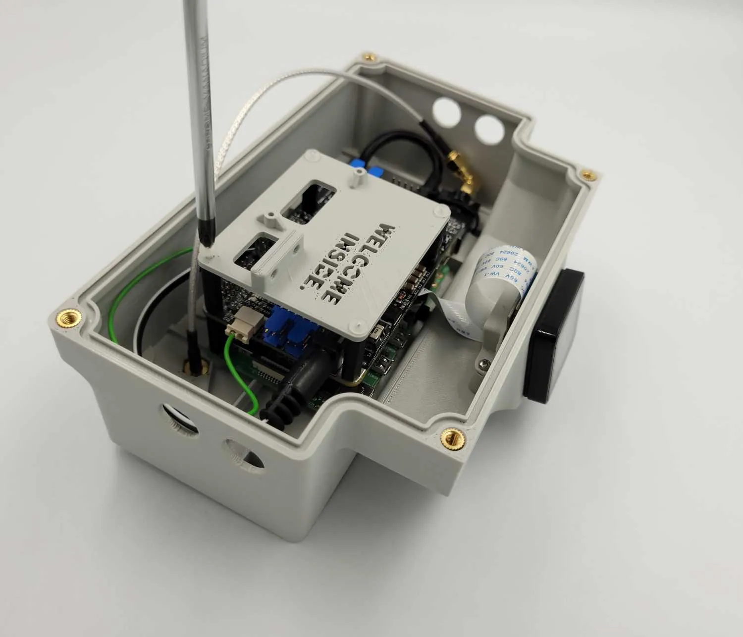
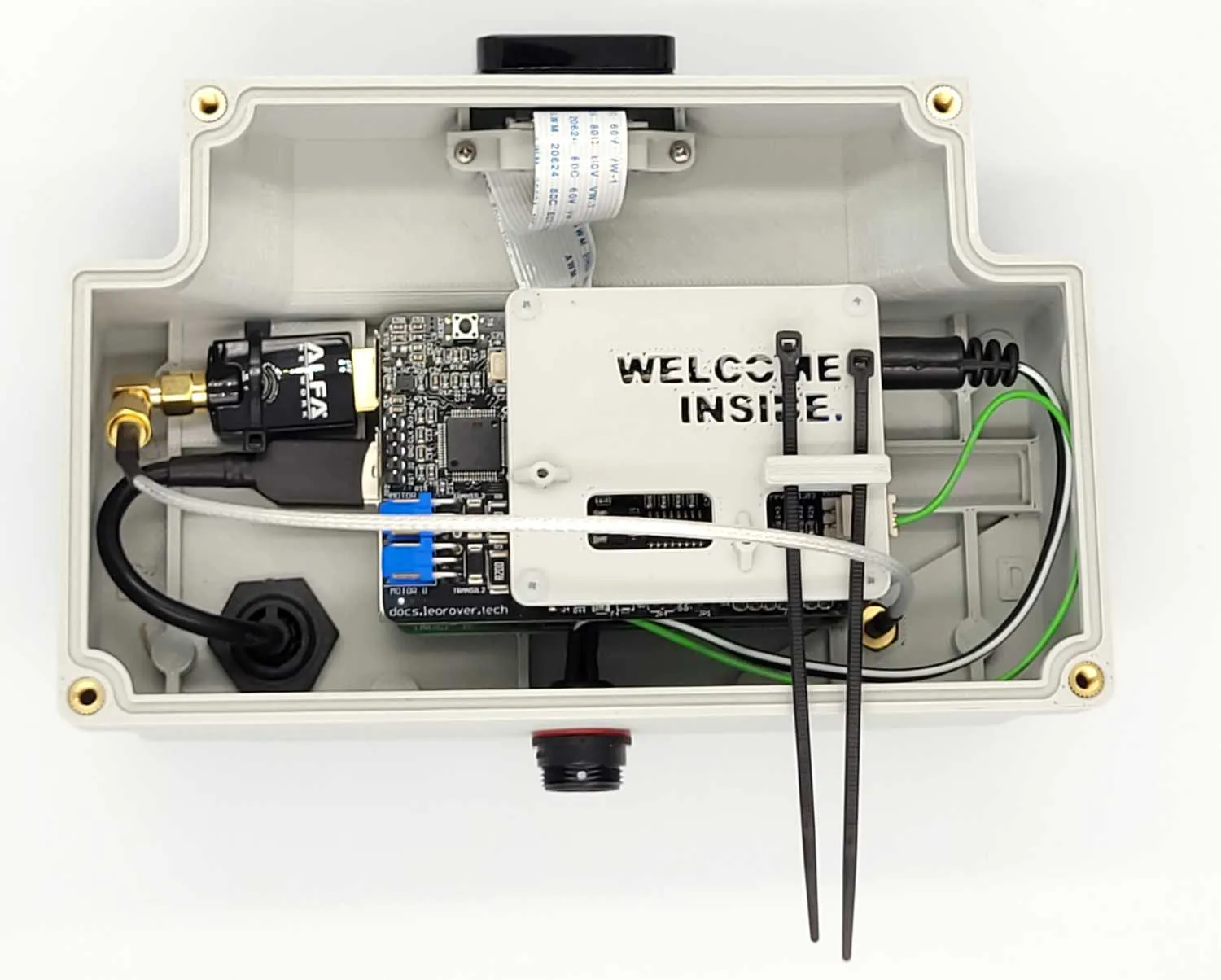
Attach the plastic cover to the electronics distances using 4x plastic screws.Don't overtighten the screws.
Thread 2 zip-ties through the electronics cover holes.
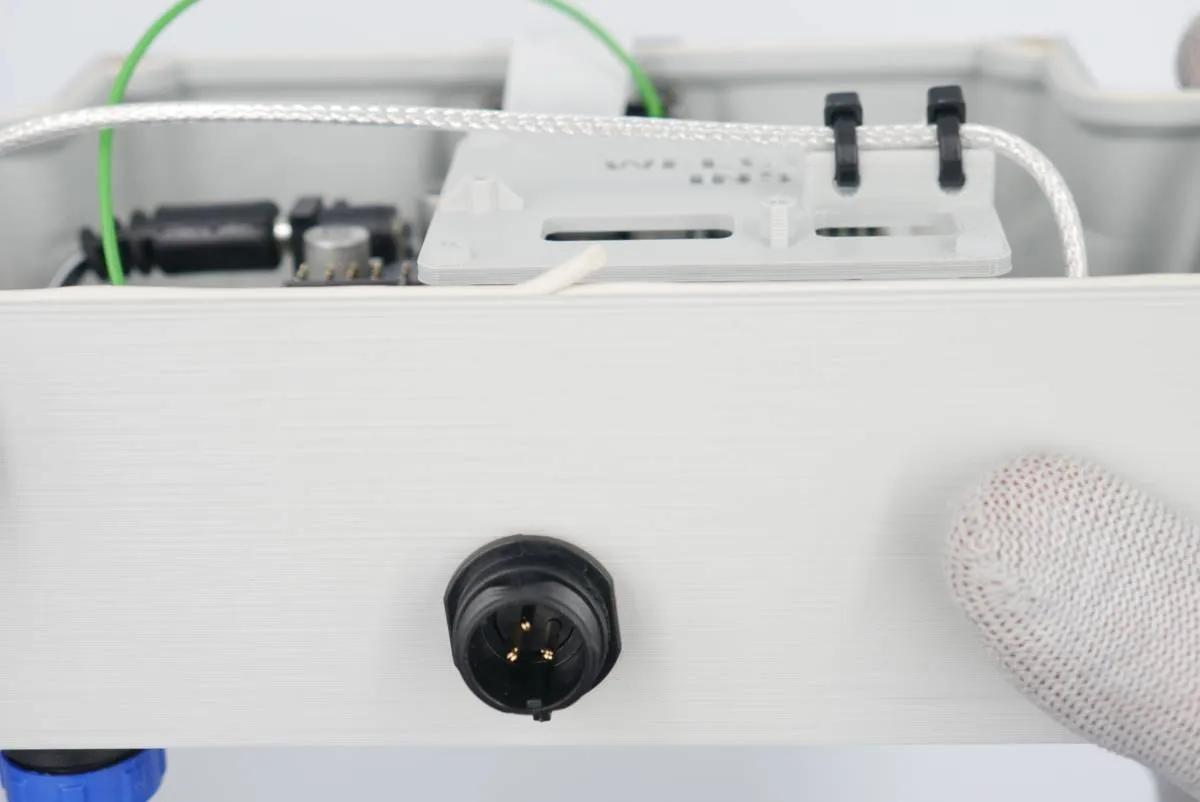
Grab the antenna cable with the zip-ties and cut the excess tie.

Step 8: MEB distances

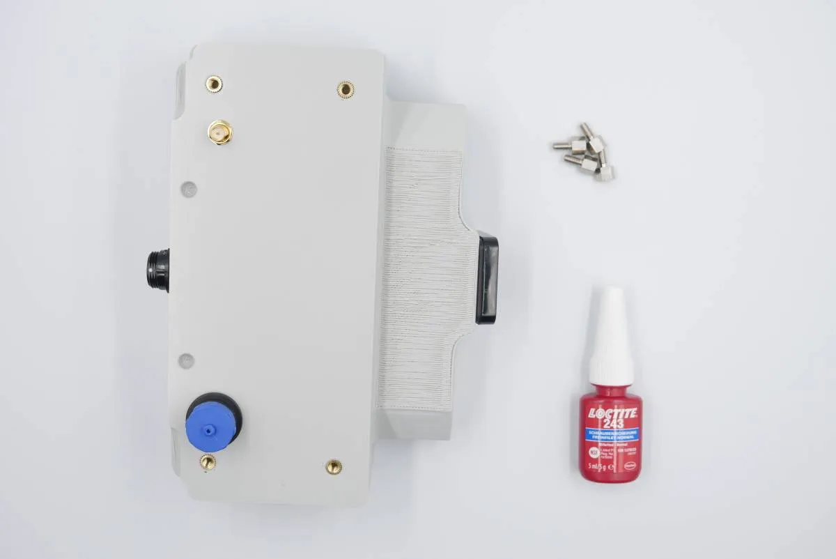
Prepare:

  • step 7 assembly
  • 4x m4x6 metal distances
  • Loctite glue
  • 7mm hex wrench
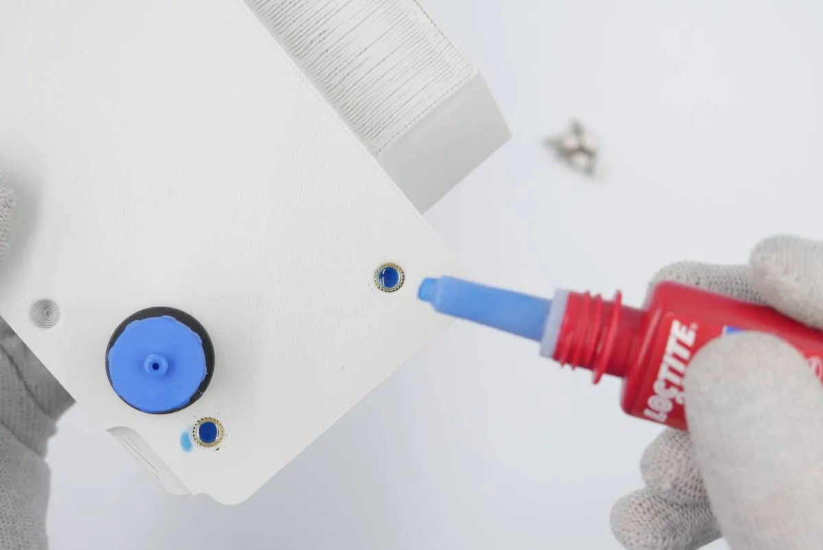
Put some Loctite in each of 4 holes in the main electronics bottom threaded inserts.
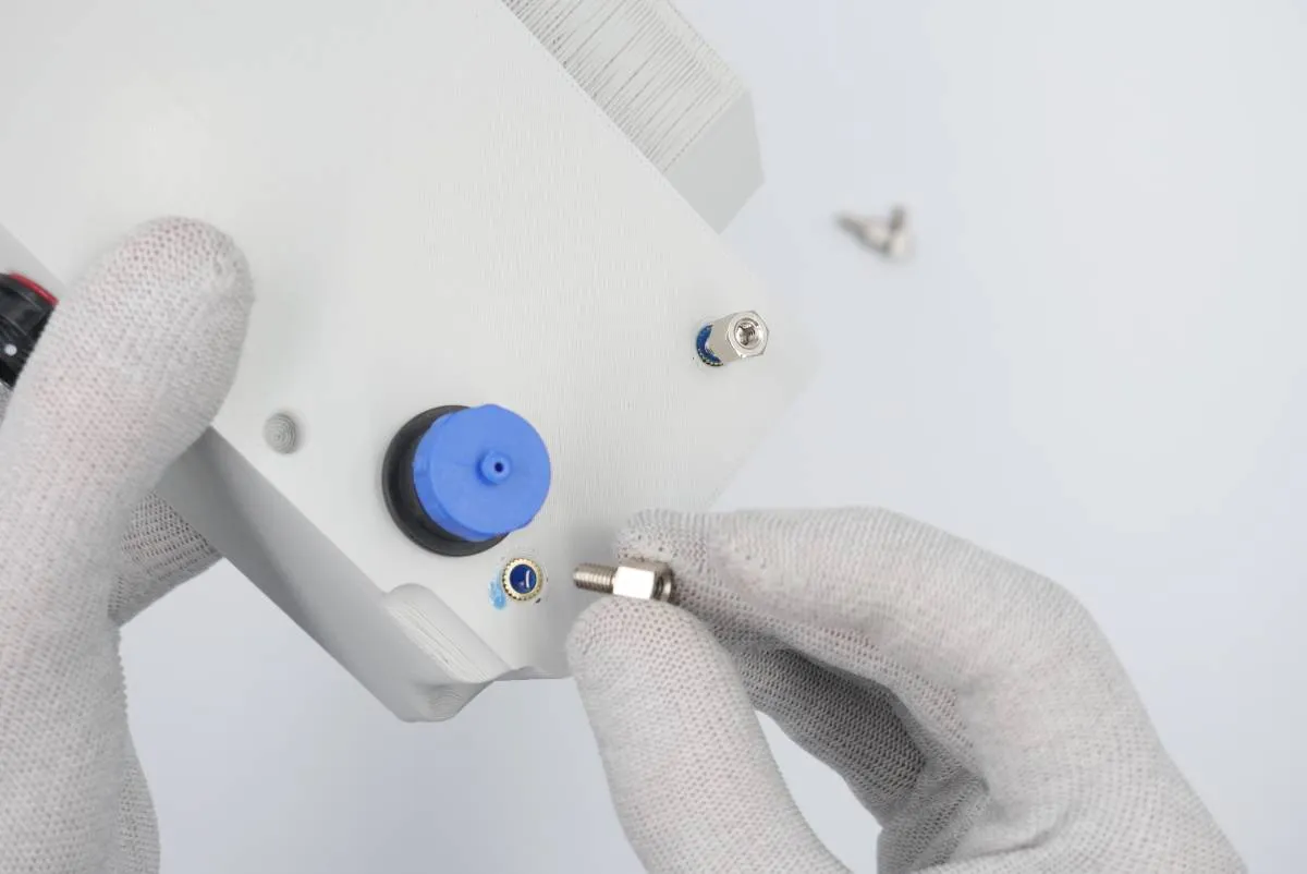
Screw and tighten each metal distance in the threaded holes. Tighten the distances only by hand as overtightening may easily cause the parts to break.

Step 9: Seal and MEB cover

Prepare:

  • step 8 assembly
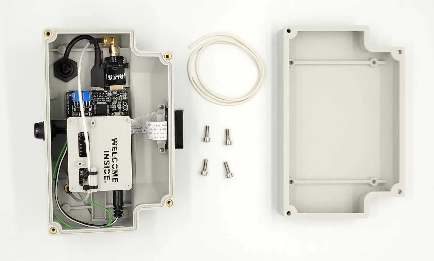
  • 1x rubber foam sealing cord
  • 4x m4x10 screws
  • 1x MEB cover (3D-printed)
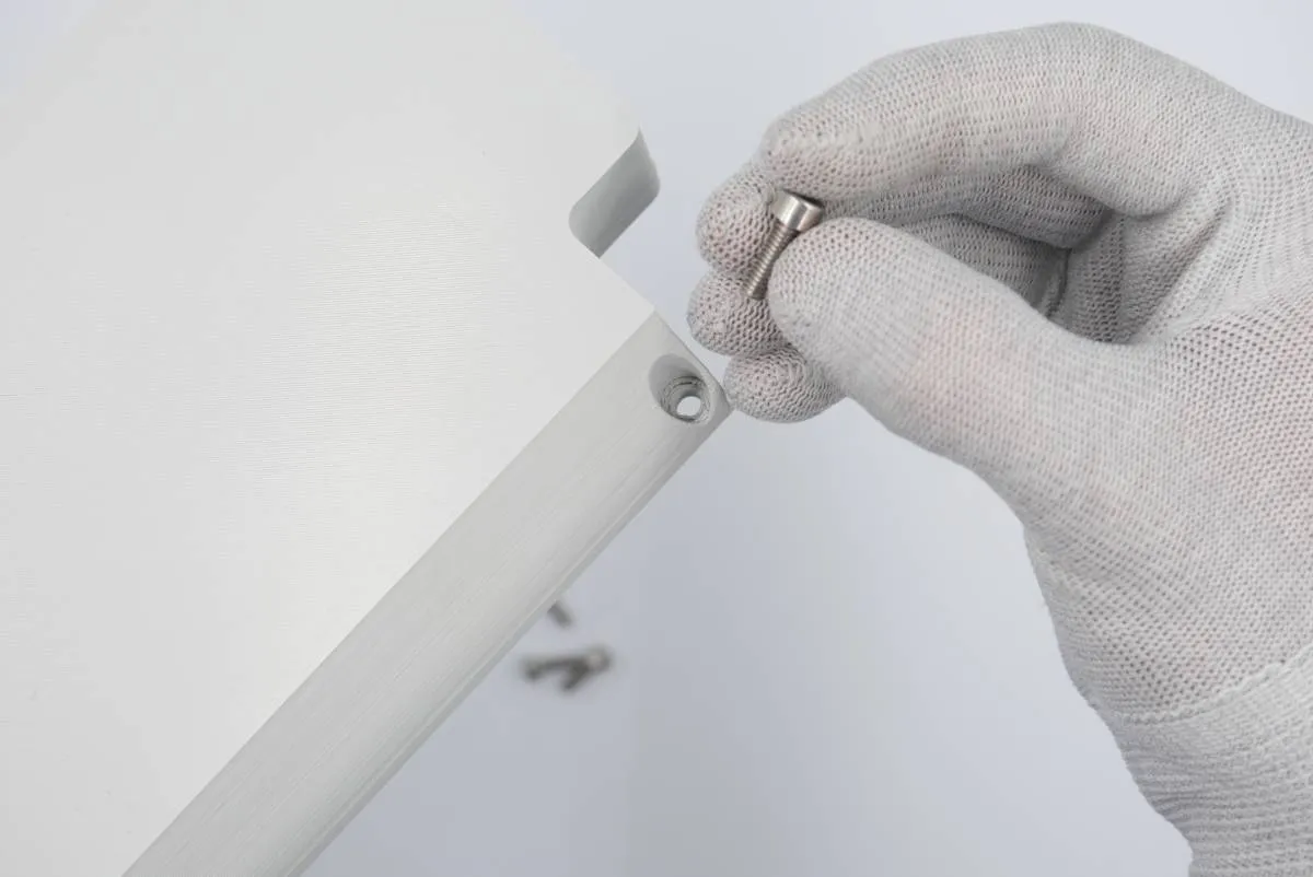
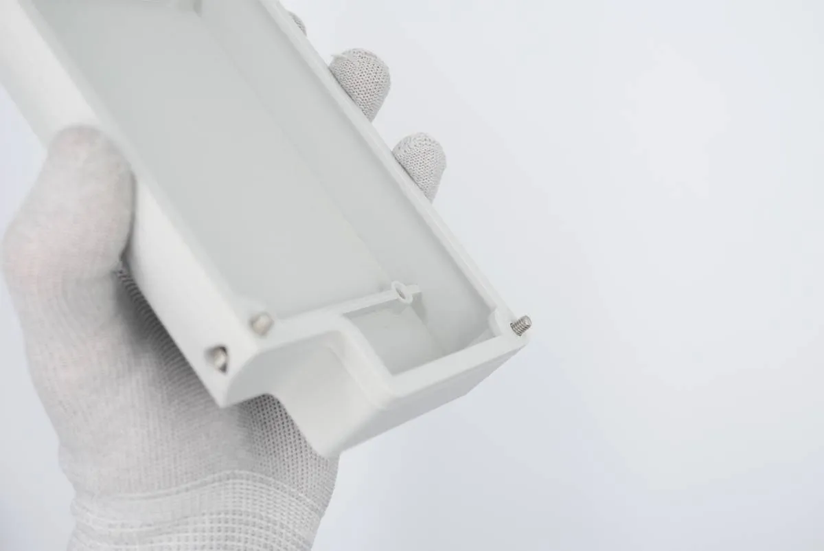
Put 4 m4x12 hex screws in the MEB cover holes (one for each corner).
Store the cover. It will be used only in the Task 8.
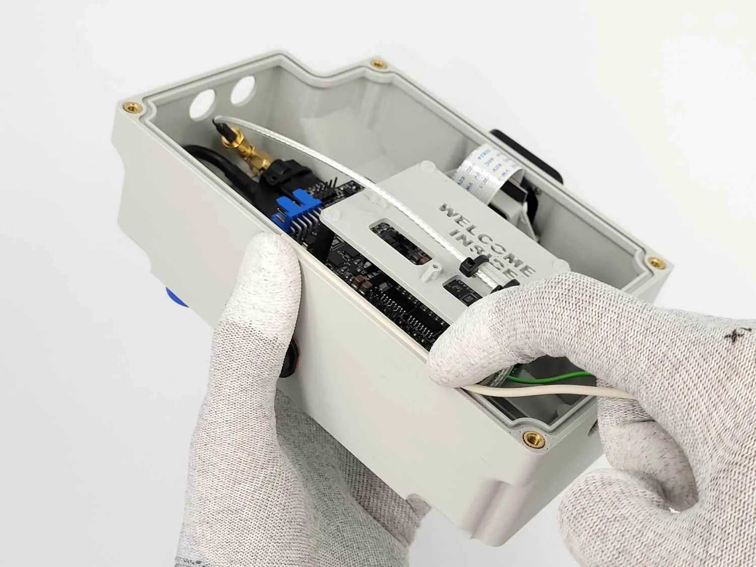
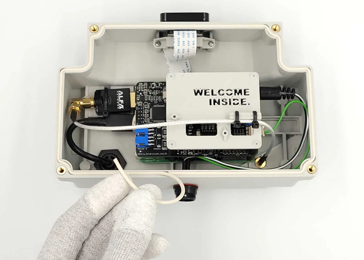
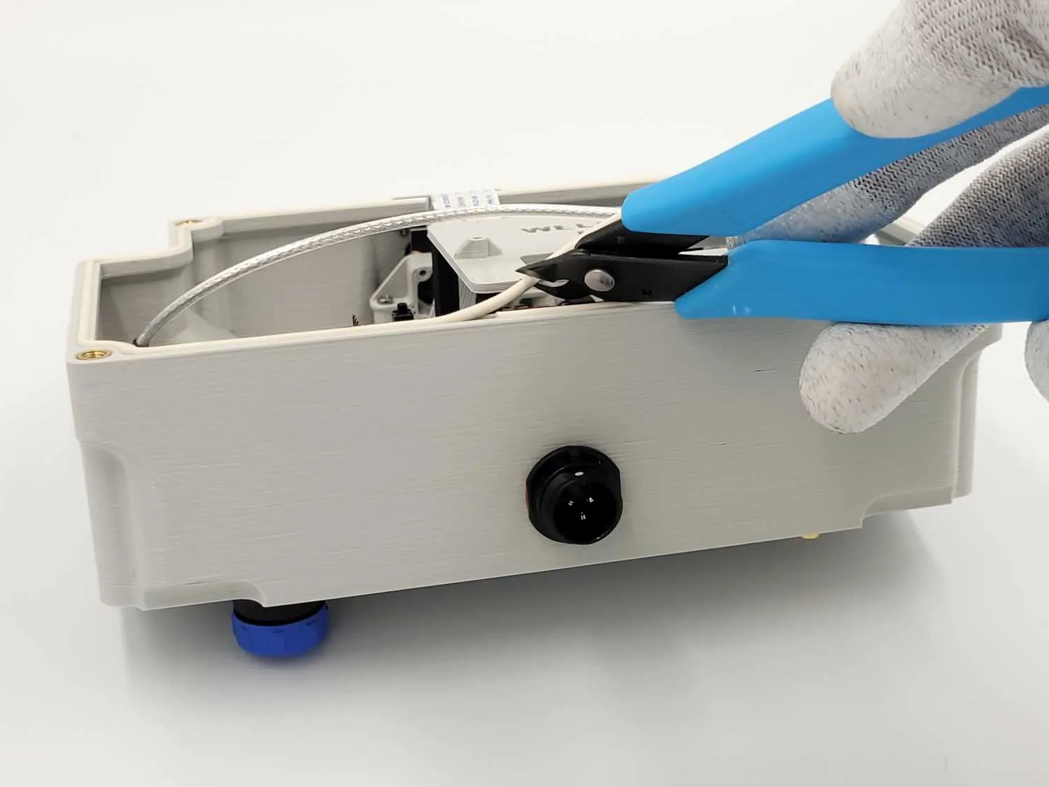
Insert the sealing cord in a corresponding groove in the main electronics box. Patience needed to go through all the groove.
Cut the excess cord. Leave just enough to let the cord overlap the other end.

Done!

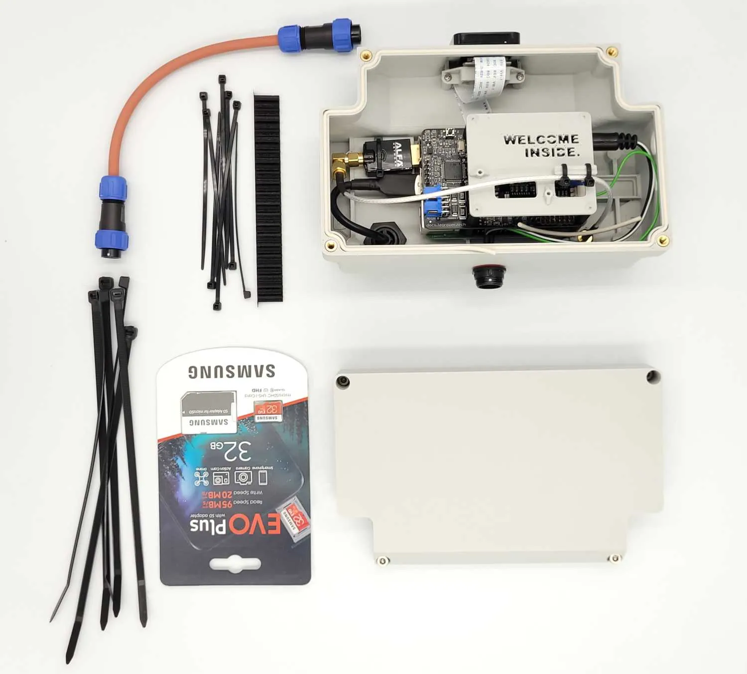
After the step you'll end up with a couple of components that were in the box, but weren't used in the step. Store them, they will become useful in the next Tasks.