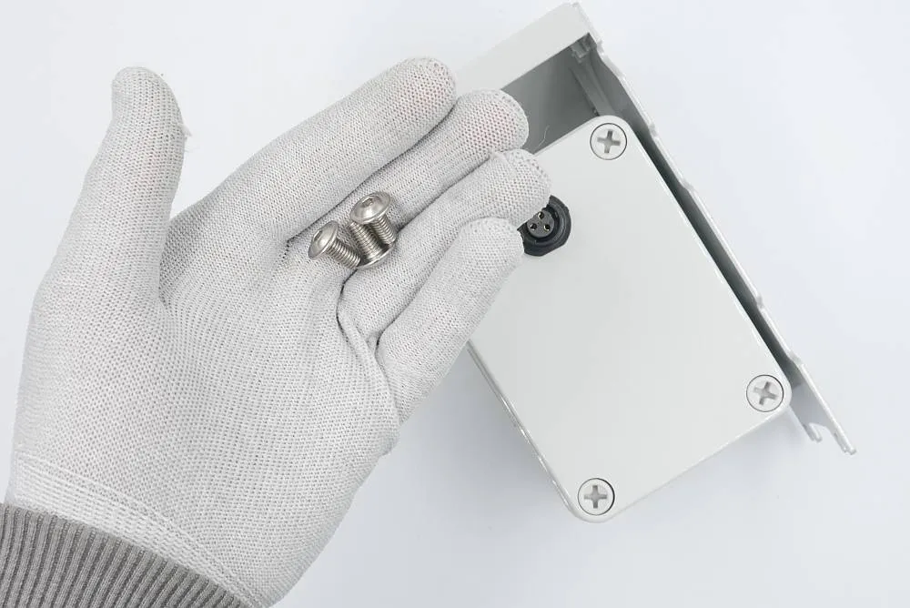
Task 4: Battery
Preparation
Assembly time
10 minutes
Tools needed
- T10 torx screwdriver
- 3mm hex-head key
- Philips cross-headed screwdriver
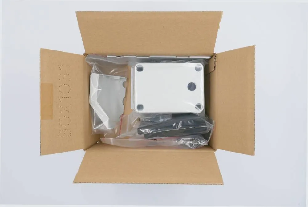
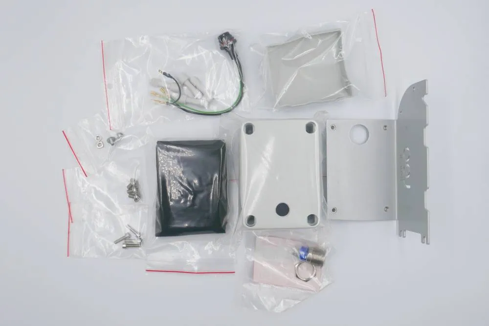

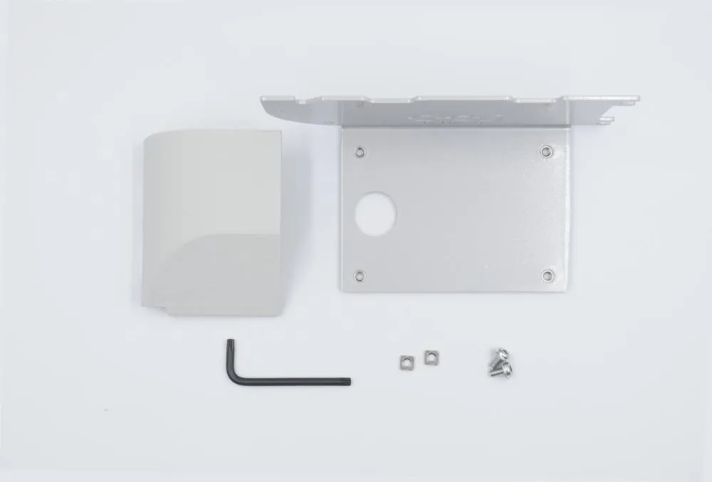
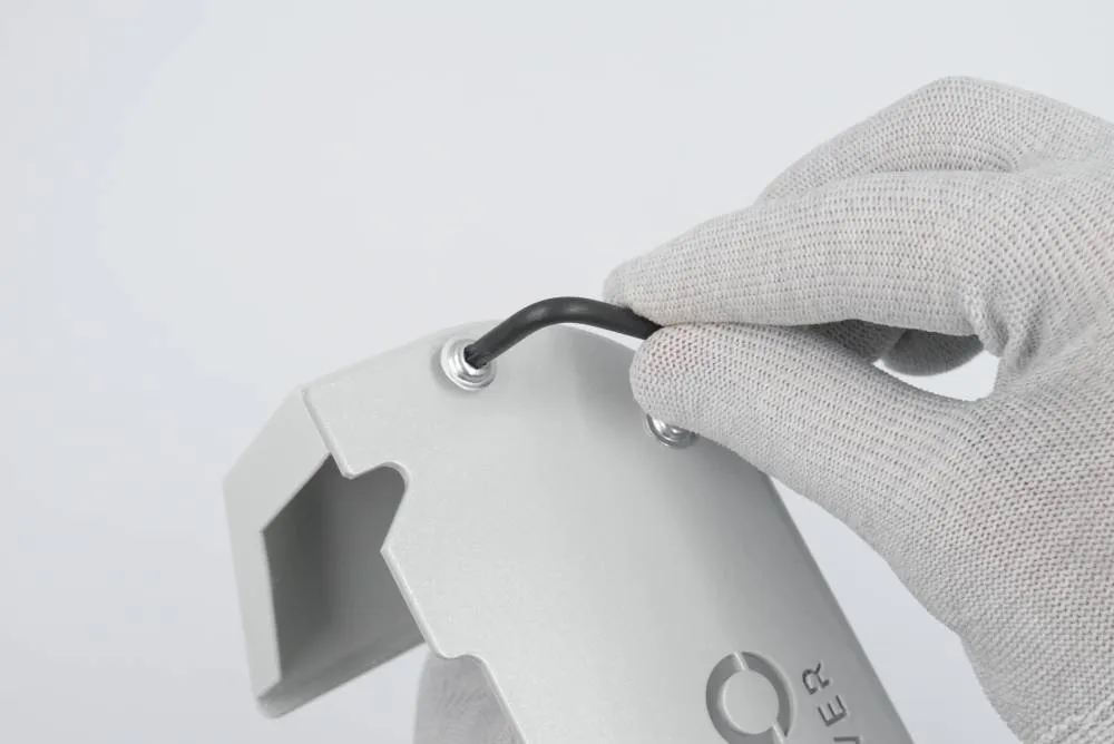
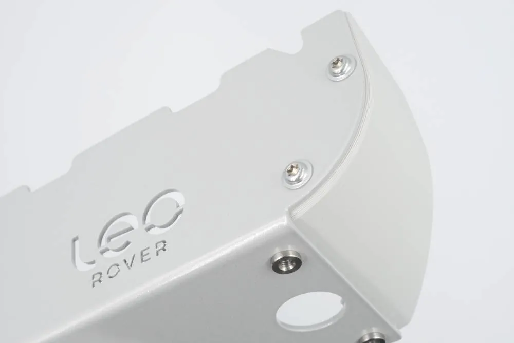
Step 1: Plastic cover
Prepare:
- 1x battery cover (3D-printed)
- 1x battery metal plate (aluminum, painted grey)
- 2x M4x8 torx screws
- 2x M4 square nuts
- T10 torx key
Step 2: Battery button
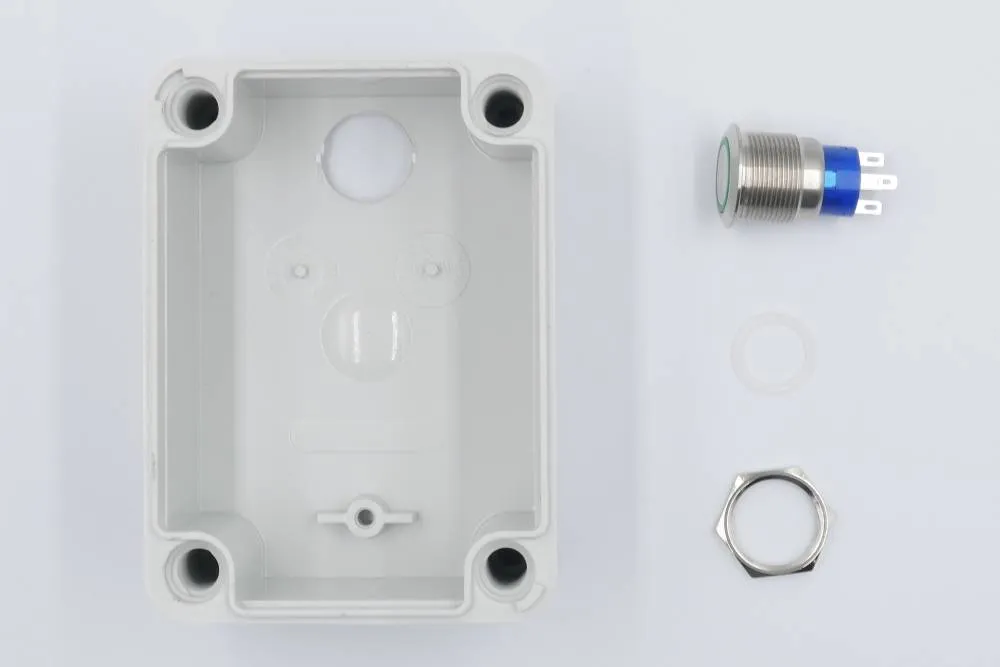
Prepare:
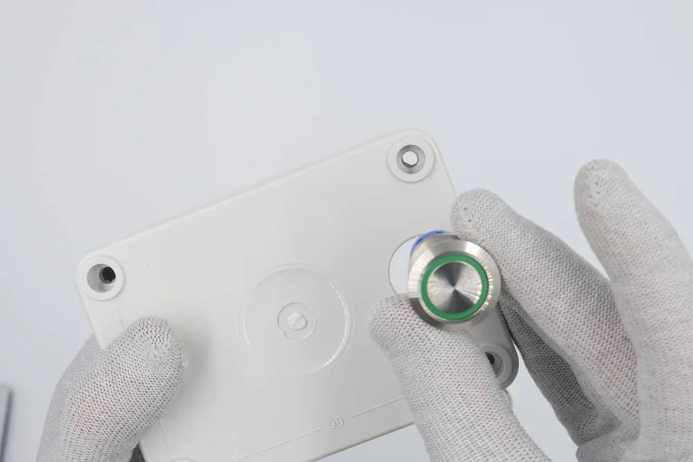
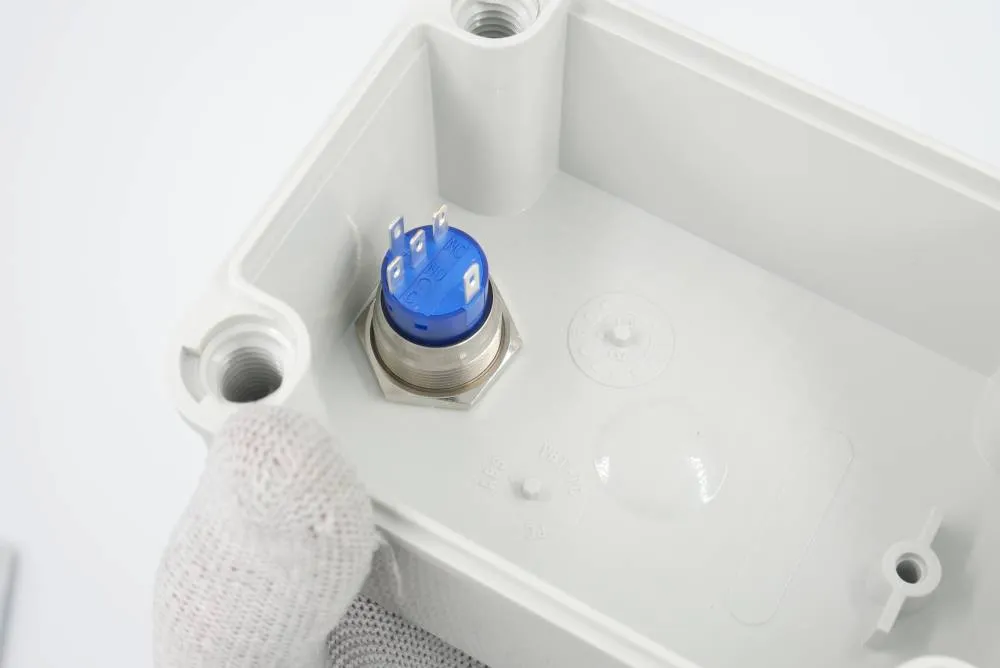
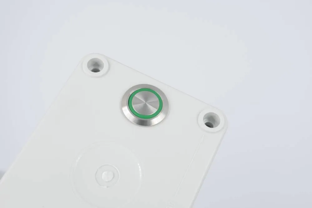
- 1x battery box
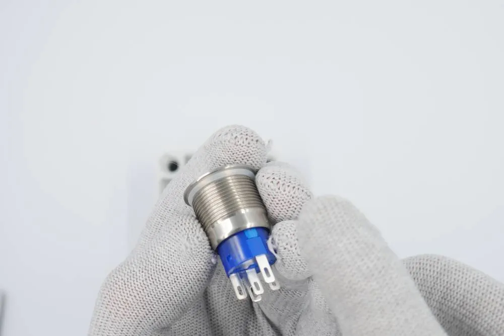
- 1x battery button
- 1x button nut
- 1x button o-ring
Step 3: Box to cover
Prepare:
- Step 1 assembly
- Step 2 assembly
- 4x M4x16 inner hex head screw
- 4mm hex key
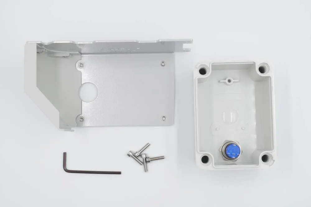
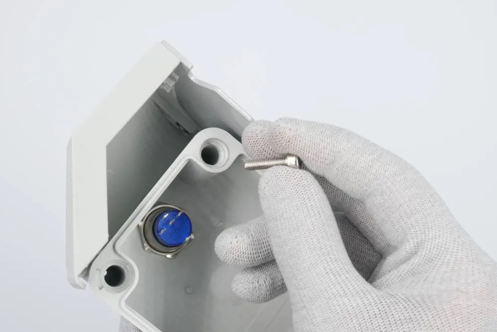
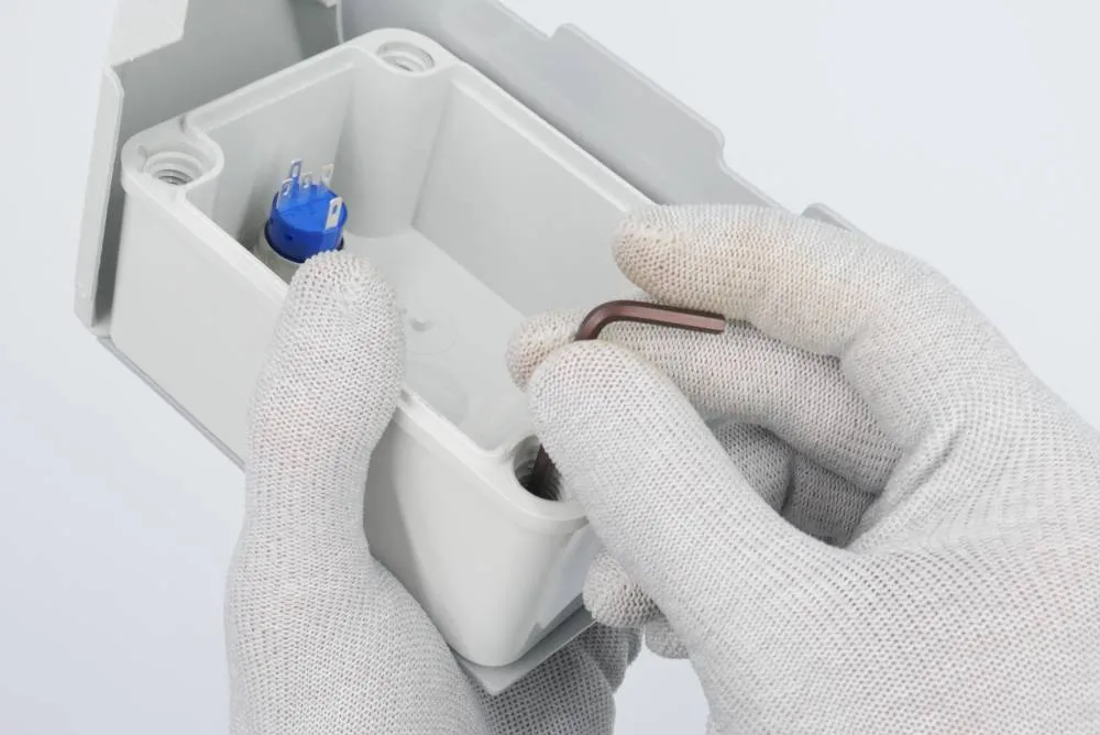
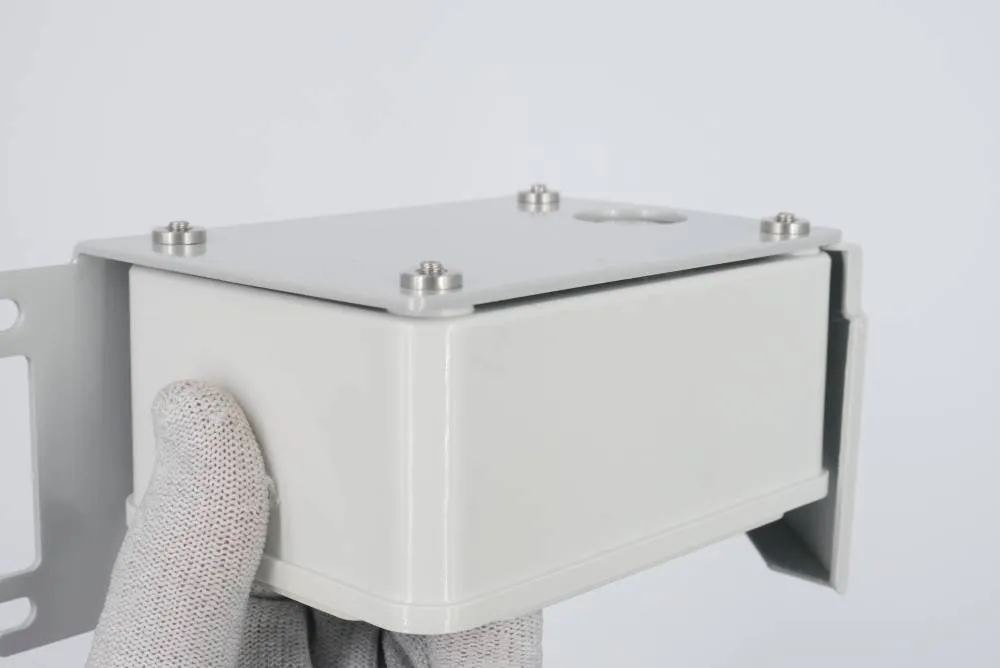
Step 4: Power connector and battery cover
Prepare:
- 1x power cable (3pin female socket with a green wire and push connectors)
- 1x power cable nut (needs to be detached from the cable beforehand)
- 4x plastic screw (big, fitting the battery cover)
- 1x battery cover
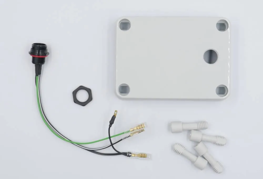
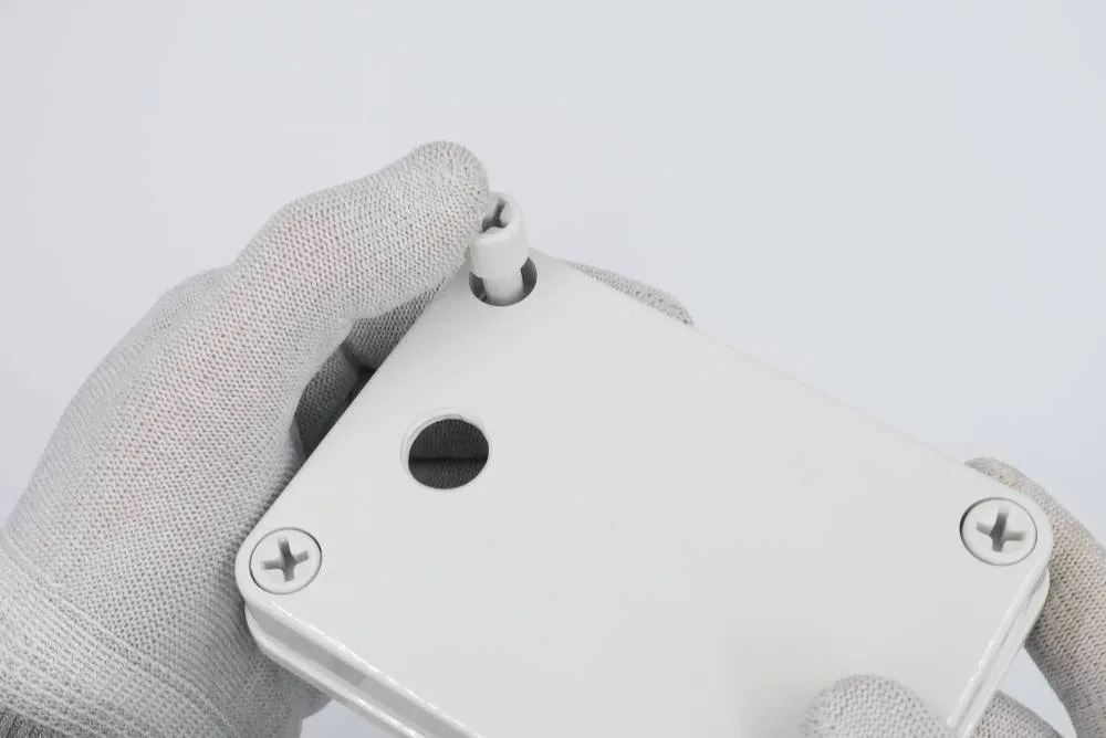
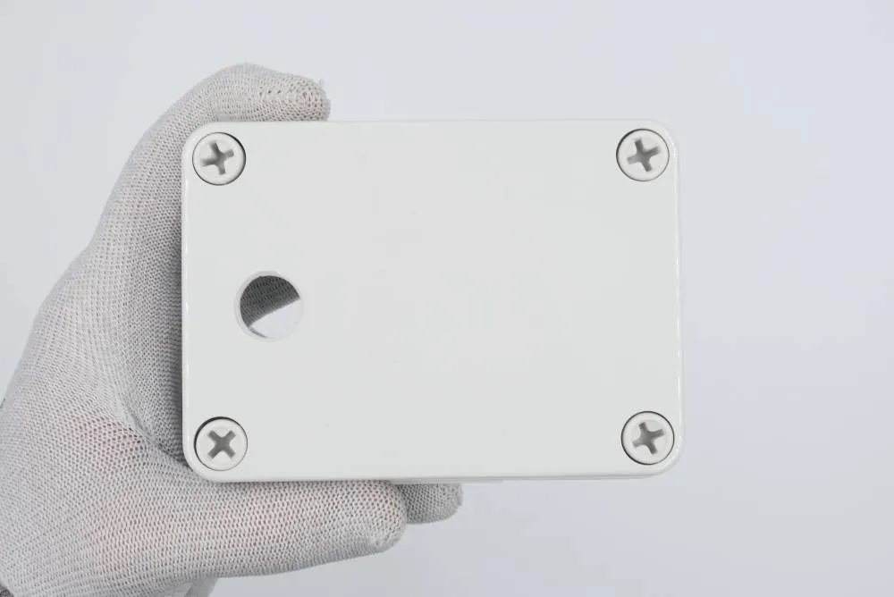
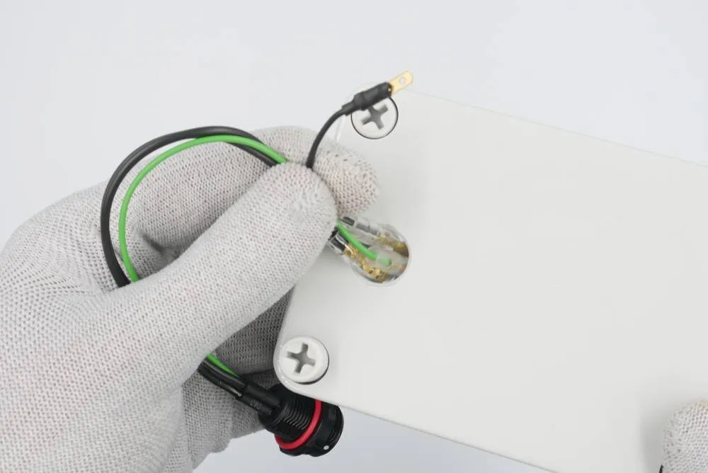
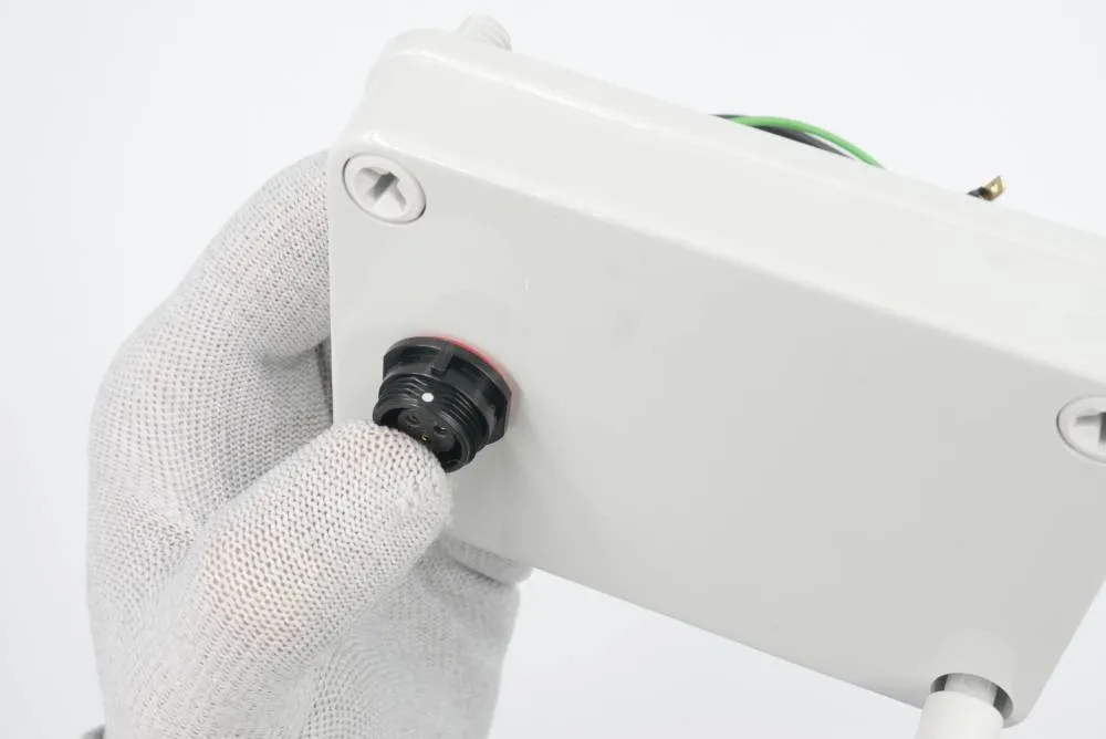
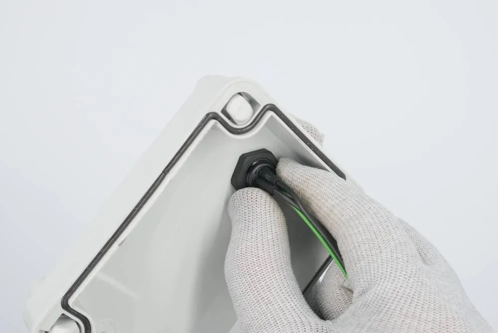
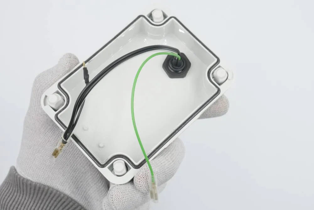
Step 5: Cable connection
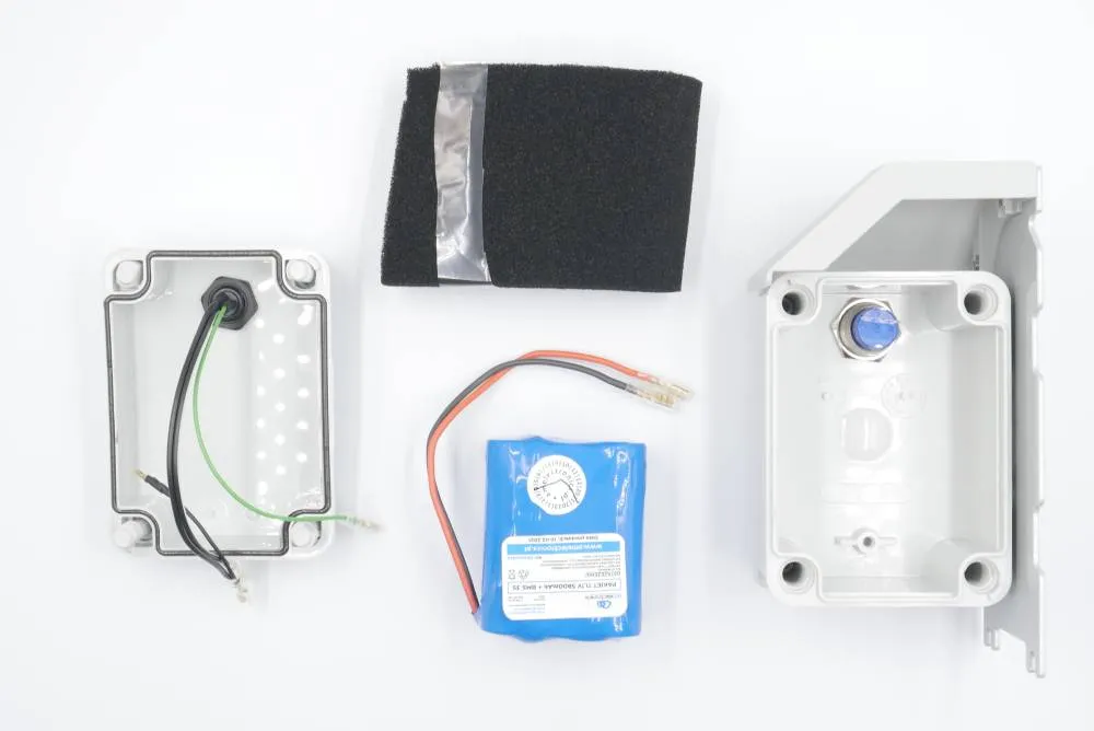
Prepare:
- Step 3 assembly
- Step 4 assembly
- 1x battery pack
List of connections:
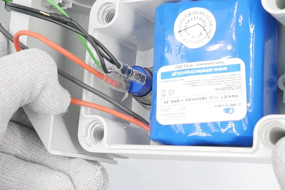
- power connector green wire to (+) pin on the button
- power connector black-with-white-stripe wire to NO pin on the button
- power connector black wire to (-) pin on the button
- battery red wire to C pin on the button
- batter black wire to power connector black wire
info
The button terminals may look different depending on a batch of components we get. When there's no marking on the left and right terminals, connect green LED wire to the left (number 1) terminal and the black negative wire to the right (number 2). There is a photo lower on the site showing the correct connections for the other type of button commonly used in our Leo Rover.
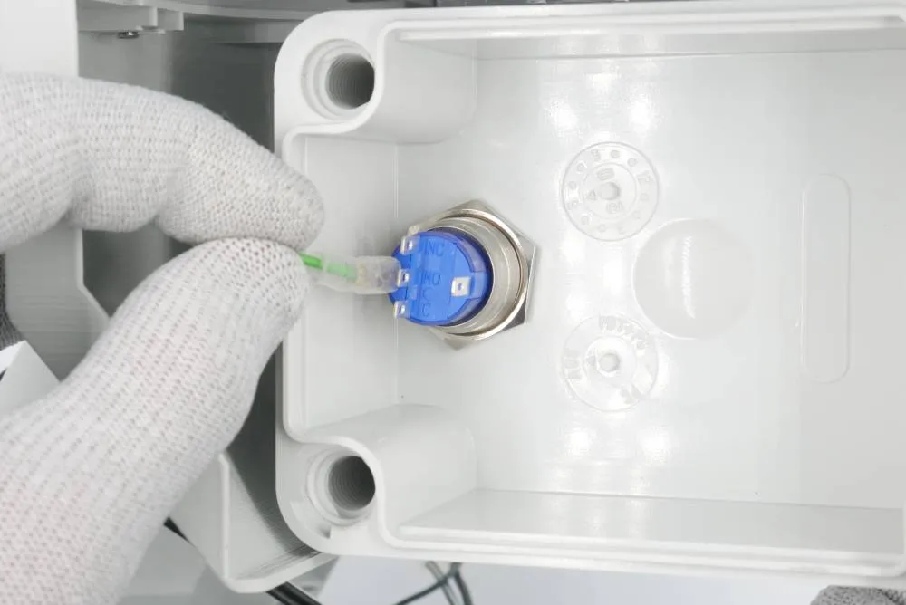
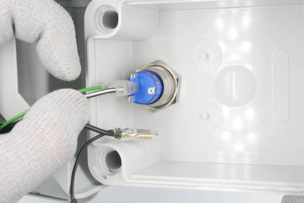
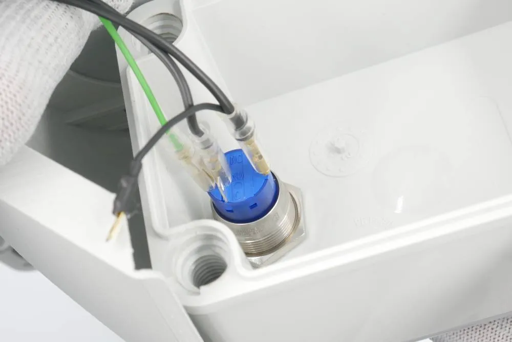
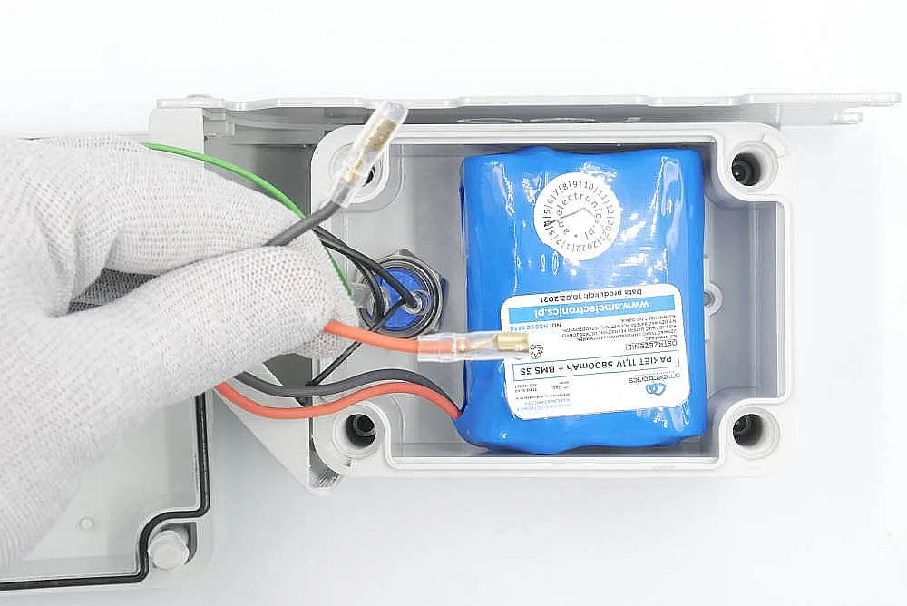
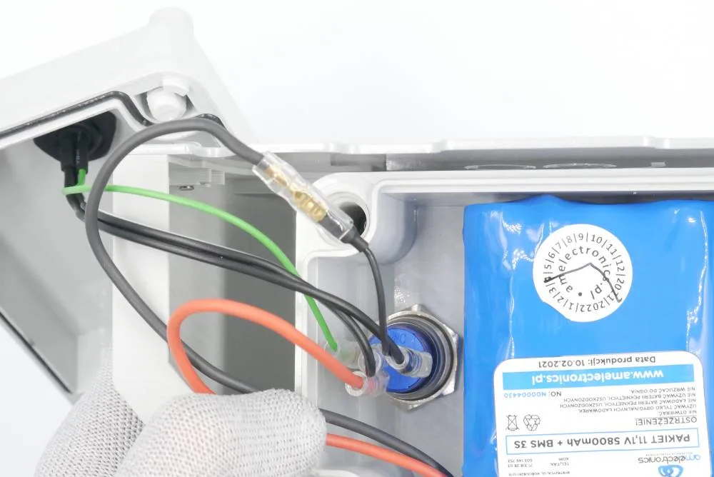
Here's a photo showing cable connections for the other button type commonly used in our rover:
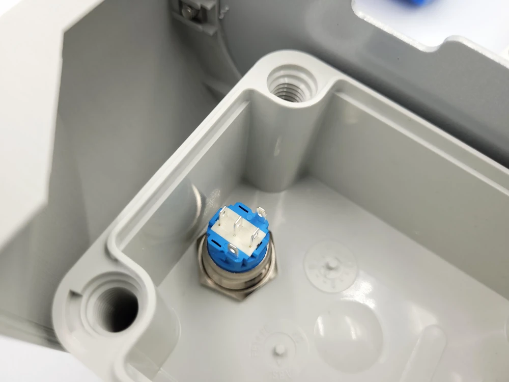
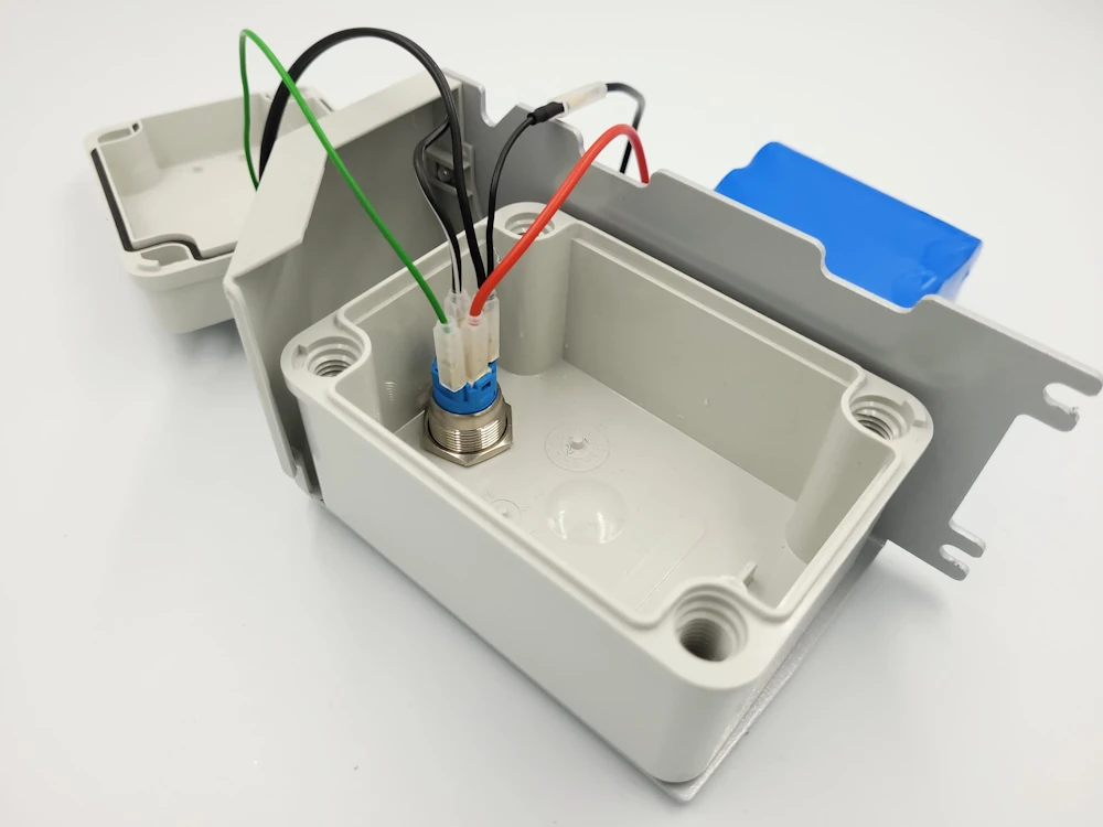
List of connections:
- Green wire connected to the leftmost pin (pin "1"),
- black and white wire connected to middle pin (pin "NO"),
- black wire connected to the rightmost pin (pin"2") and to the black battery cable.
- Red battery cable connected to the bottom pin (pin "C")
Step 6: Battery box cover
Prepare:
- Step 5 assembly
- 1x foam
- Philips cross-headed screwdriver
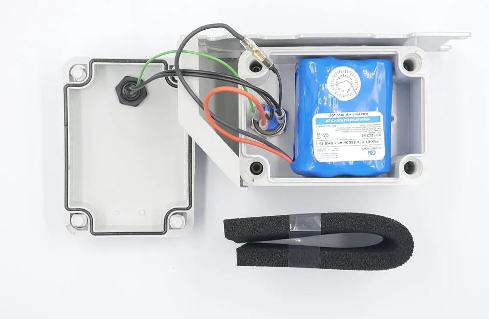
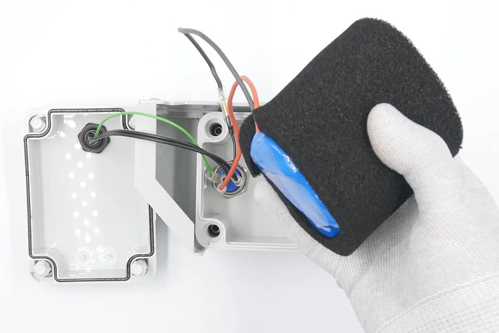
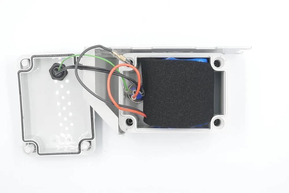
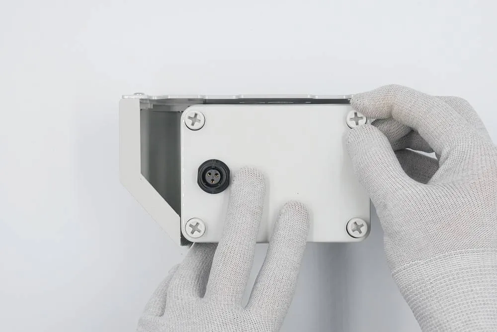
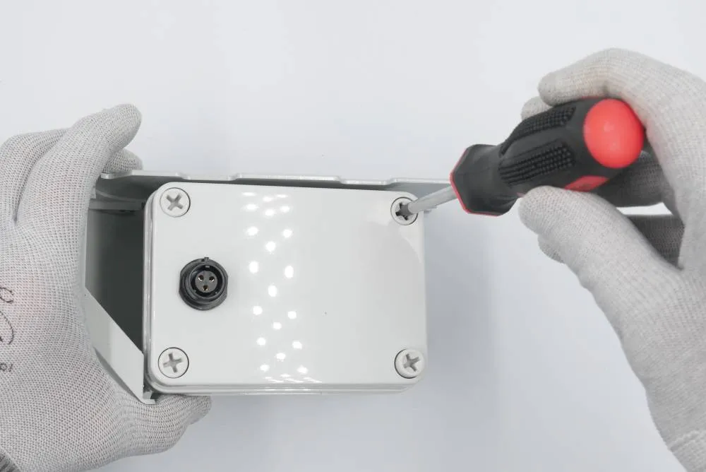
Nice and tidy. Now it's time to put everything together.
