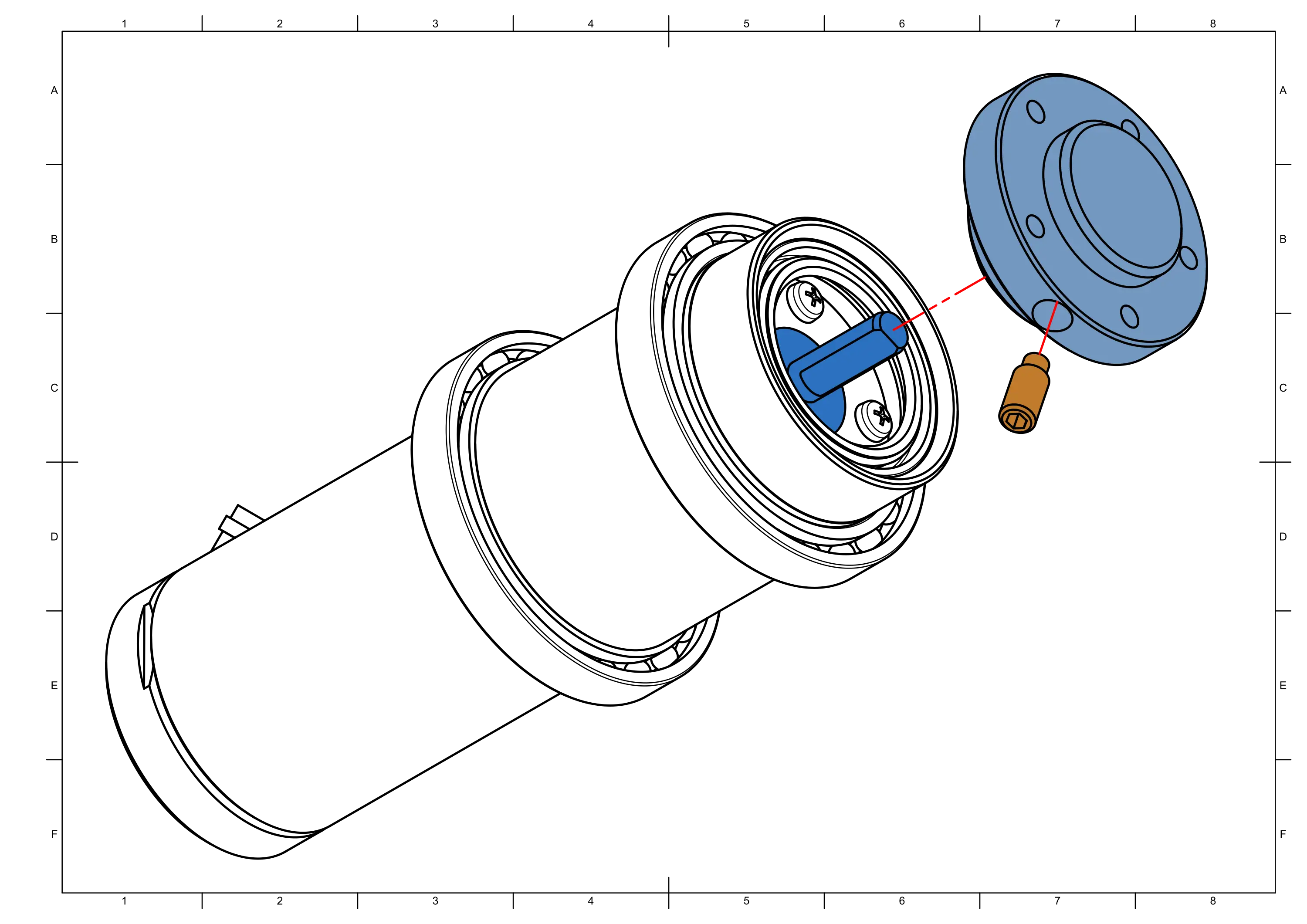
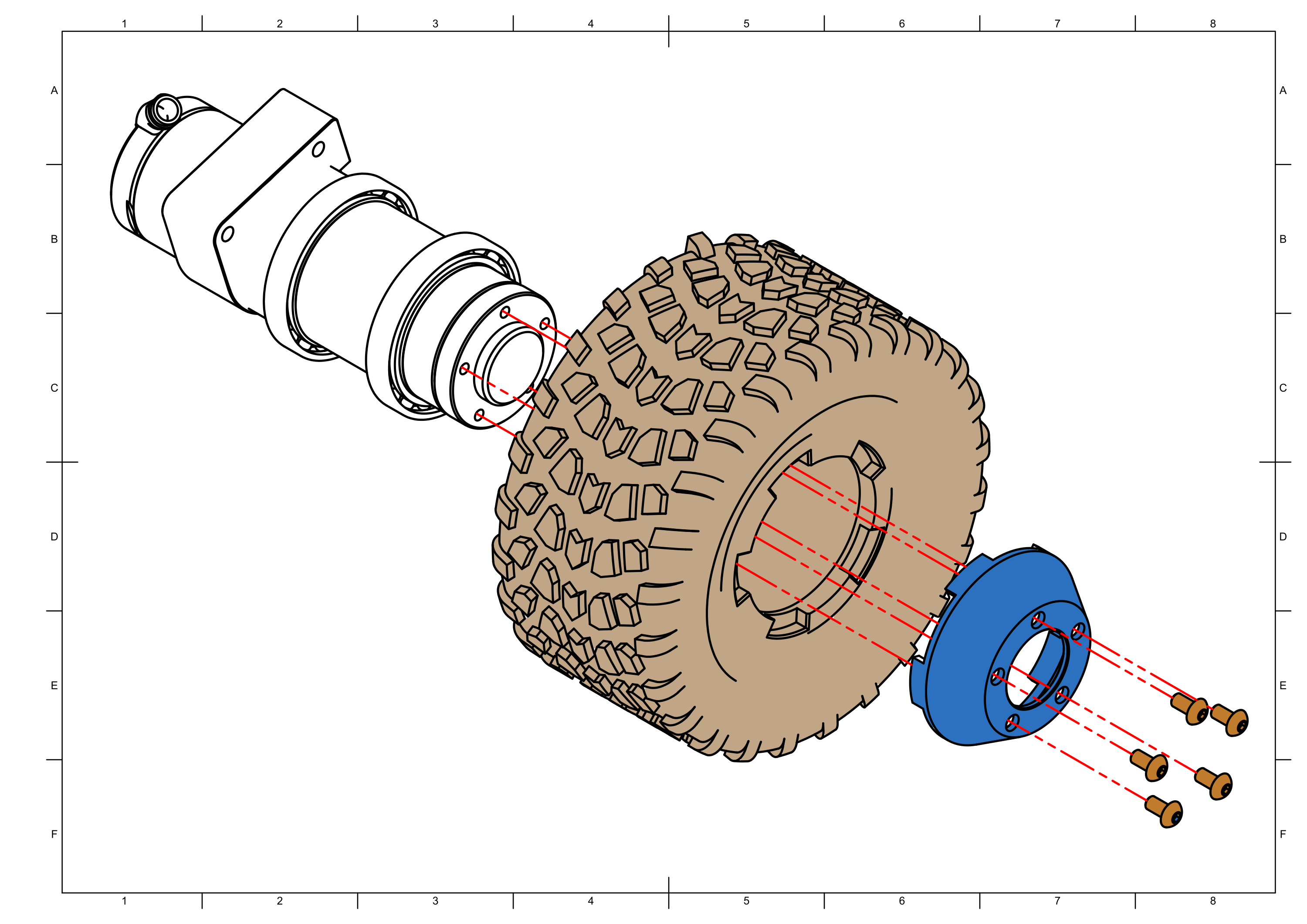
Task 1: Wheel Assembly
Assembly time ≈ 15 minutes per wheel


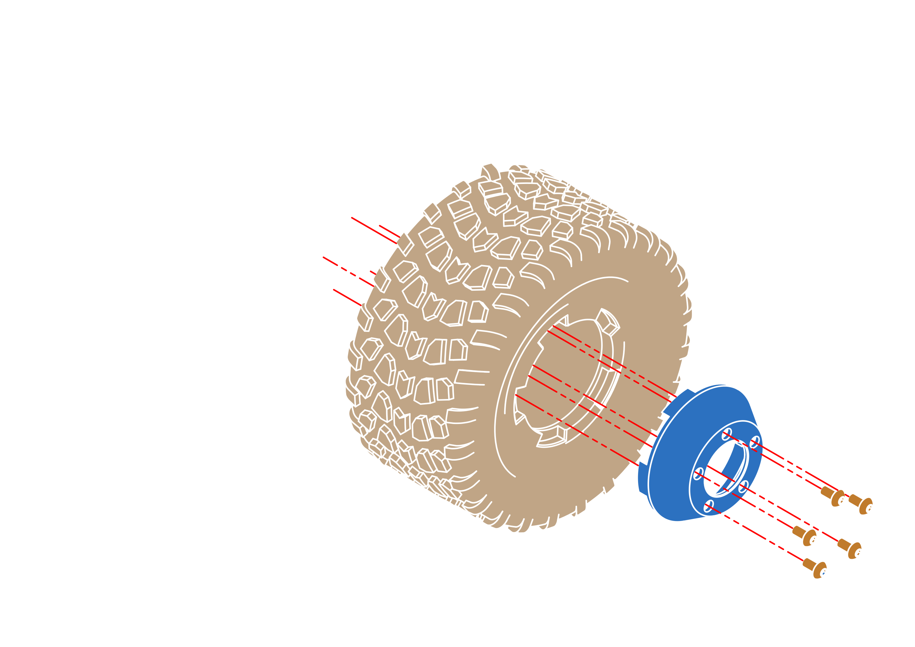
Step 1


note
Press a decent amount of lithium grease between the shaft seal and the motor housing.

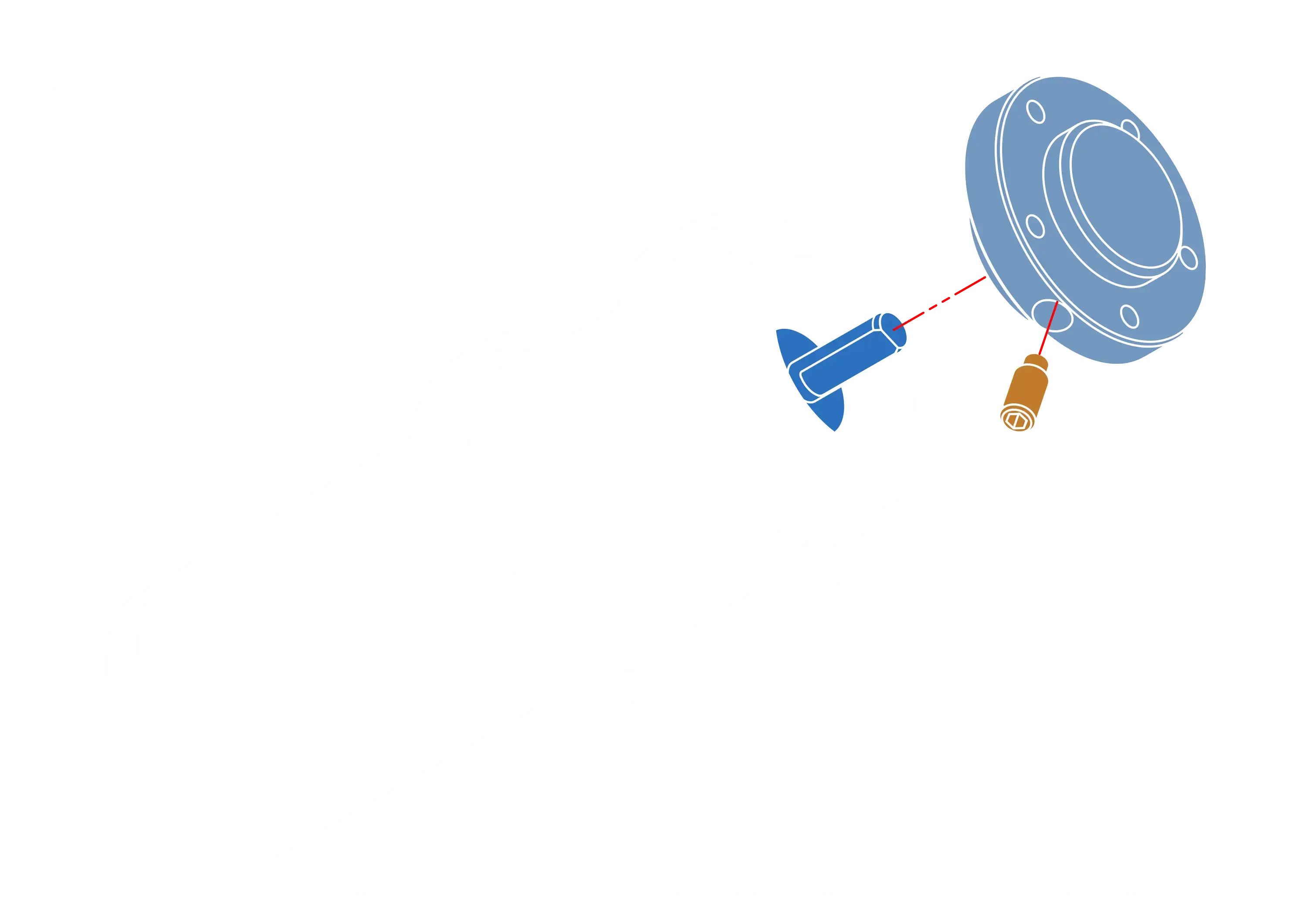
Step 2


note
Align the flat segment of motor shaft with headless screw. Use a drop of loctite to make sure it stays in place.

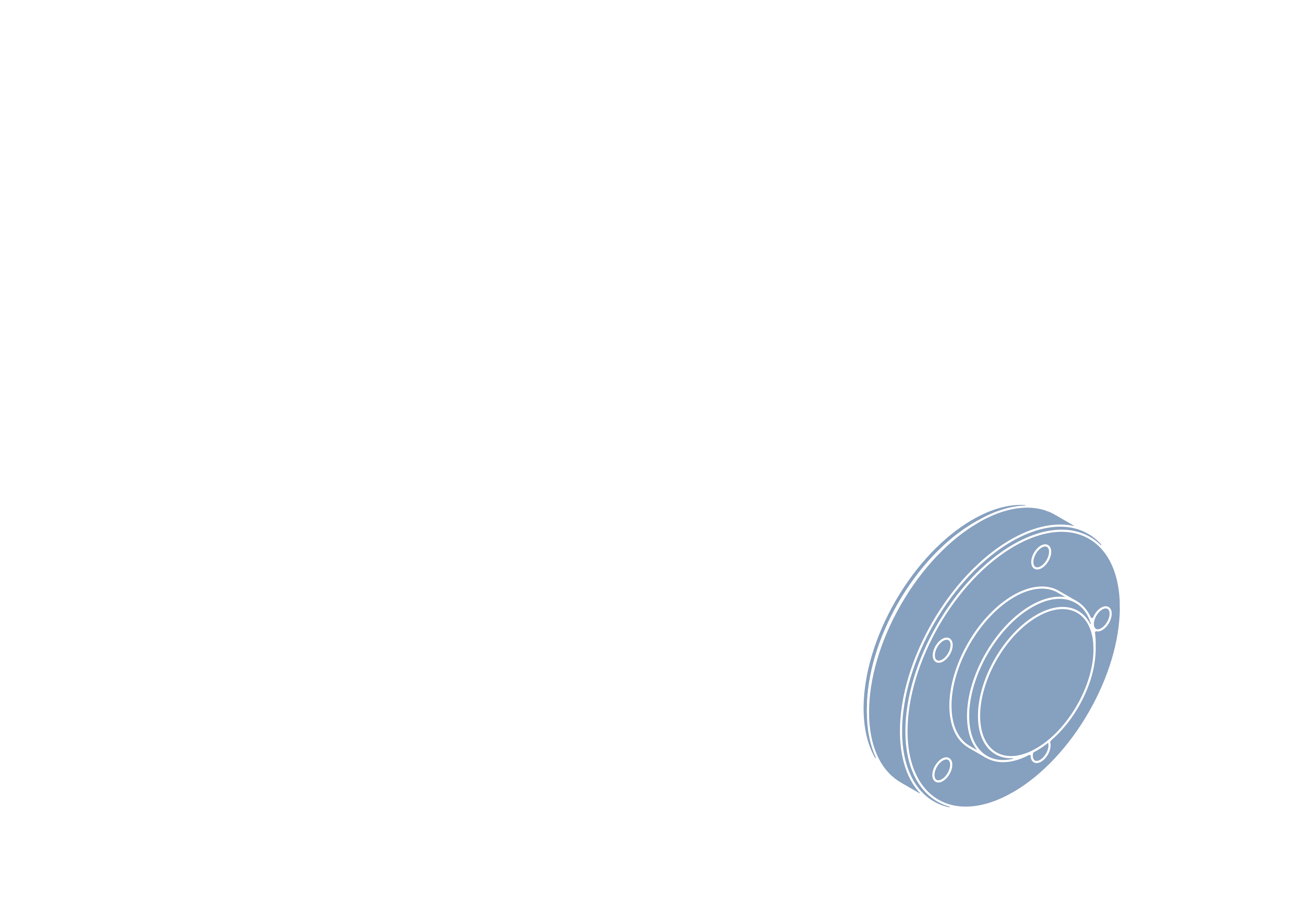
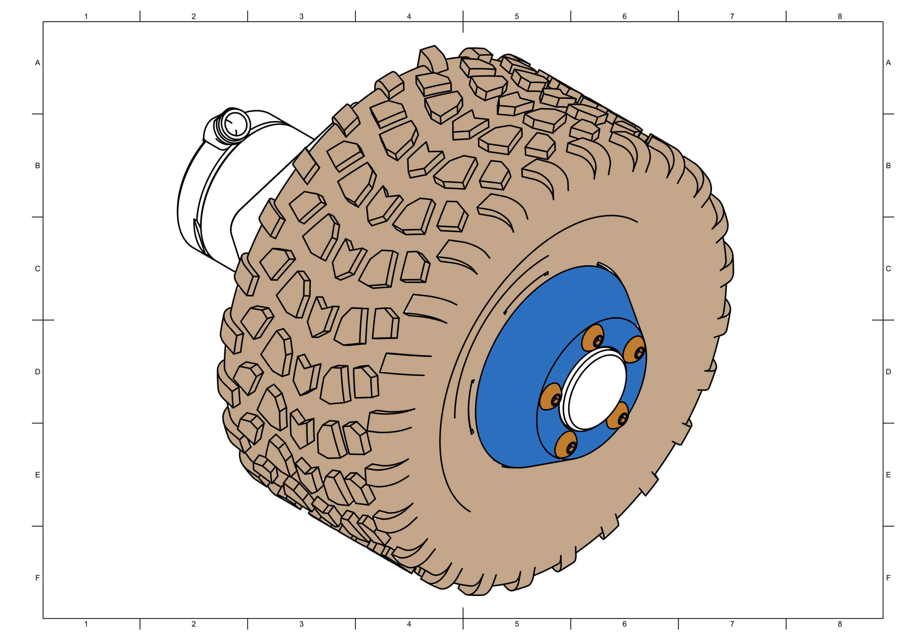
Step 3


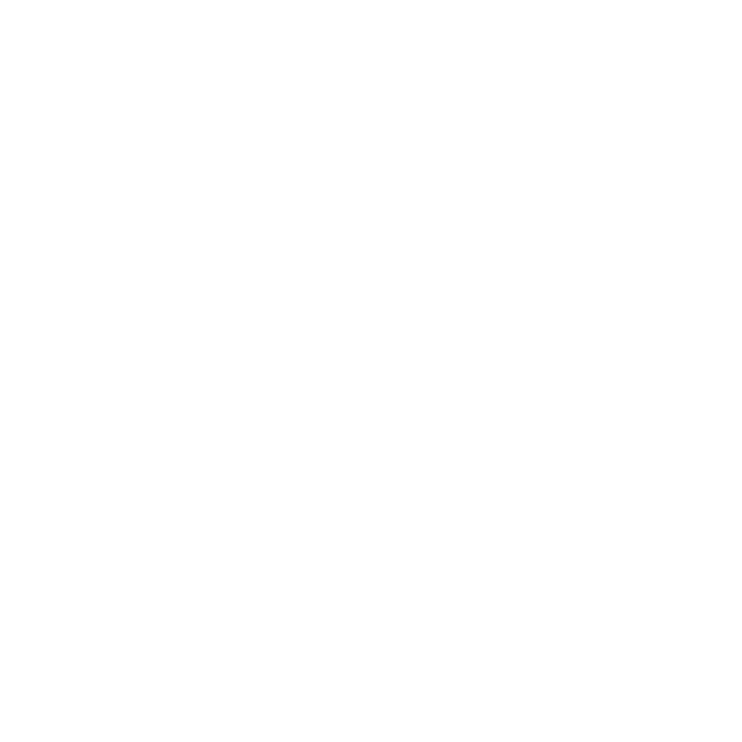
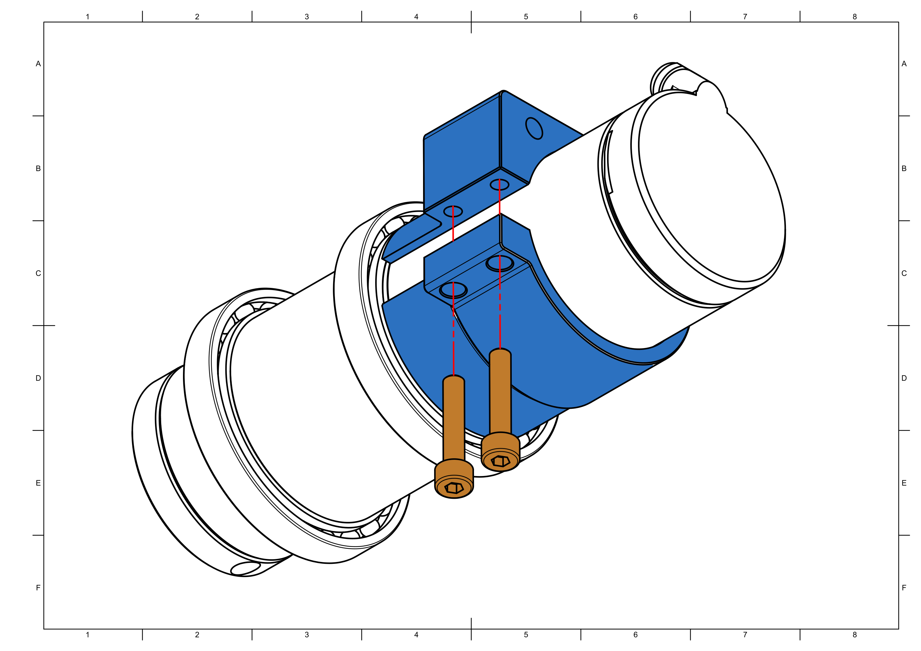
note
Slide the motor mount forward until it touches the base of the bearing before tightening.

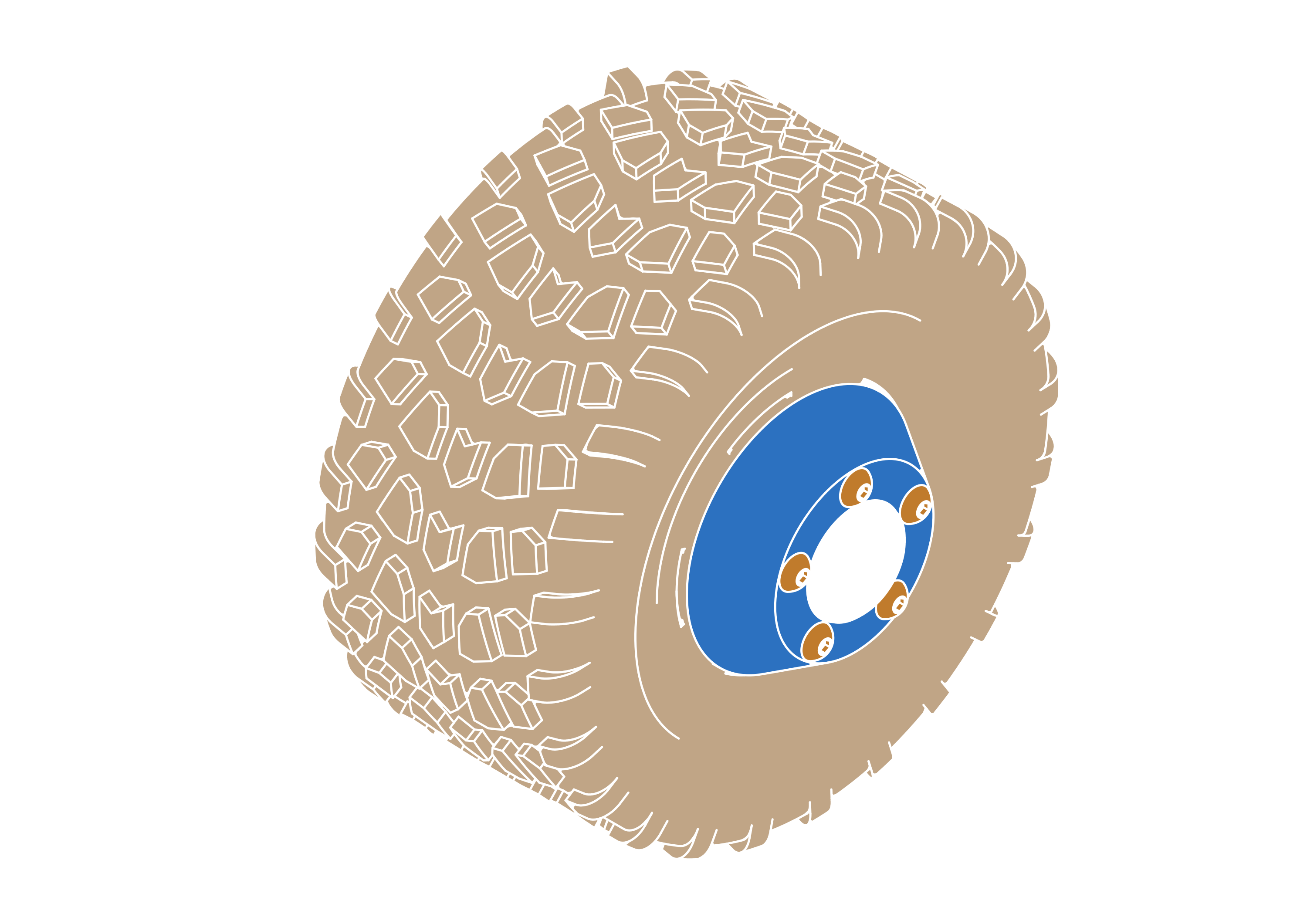
Step 4


info
Repeat until you have a total of 4 wheels.