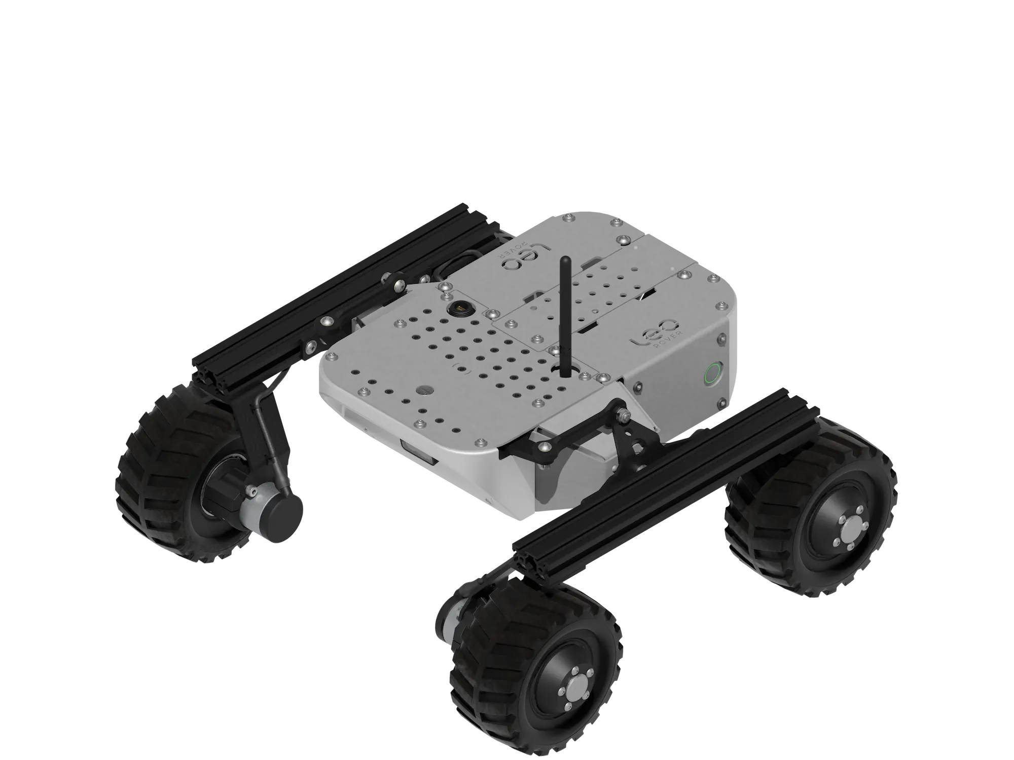
Leo Rover Specification (v1.8)
Size and Performance
Weight: 6,5 kg
Dimensions: 425x448x305 mm
Maximum linear speed: ~0.4m/s
Maximum angular speed: ~60 deg/s
Estimated maximum obstacle size: 70mm
Protection rating: IP55 compliant
Run time: Estimated 4 hours of nominal driving
Connection range: Up to 100m (with live video stream)
Dimensions


Payload
Payload capacity: ~5 kg
Upper mounting platform dimensions: 299 x 183 mm
Hole grid: 18 x 15 mm
Holes: 40 x Φ7mm + 22 x Φ5,5mm
Connection interfaces
- miniUSB waterproof socket
- WiFi access point
Components
Wheels
Motors: 4 x in-hub DC motor with 73.2:1 planetary gearbox and 12 PPR encoder
Tire material: rubber with foam insert (non-pneumatic)
Inner rim diameter: 71 mm
Outer tire diameter: ~130 mm
Tire width: ~70 mm
Battery
Voltage: 11.1 V DC
Capacity: 5800 mAh
Type: 3S Li-Ion with internal BMS
Safety features:
- short-circuit
- overcurrent
- discharge protection
Max. current: 8A (total for whole Rover)
Estimated 4 hrs battery life (nominal driving)
Camera
Camera resolution: 5 MPx
Lens: Fisheye with 160 degree diagonal field of view (IR non-filtered;
night-vision allowed)
Network
WiFi 2.4 or 5 GHz access point with external antenna
WiFi 2.4 or 5 GHz on internal RPi antennas for connectivity
Electronics
Raspberry Pi 4B as an on-board computer
LeoCore as a real-time microcontroller
Internal open interfaces
Raspberry Pi:
- USB x2
- GPIO x20
- RJ45 Ethernet
- RPi display port
- Bluetooth 5.0 with BLE
Hardware structure
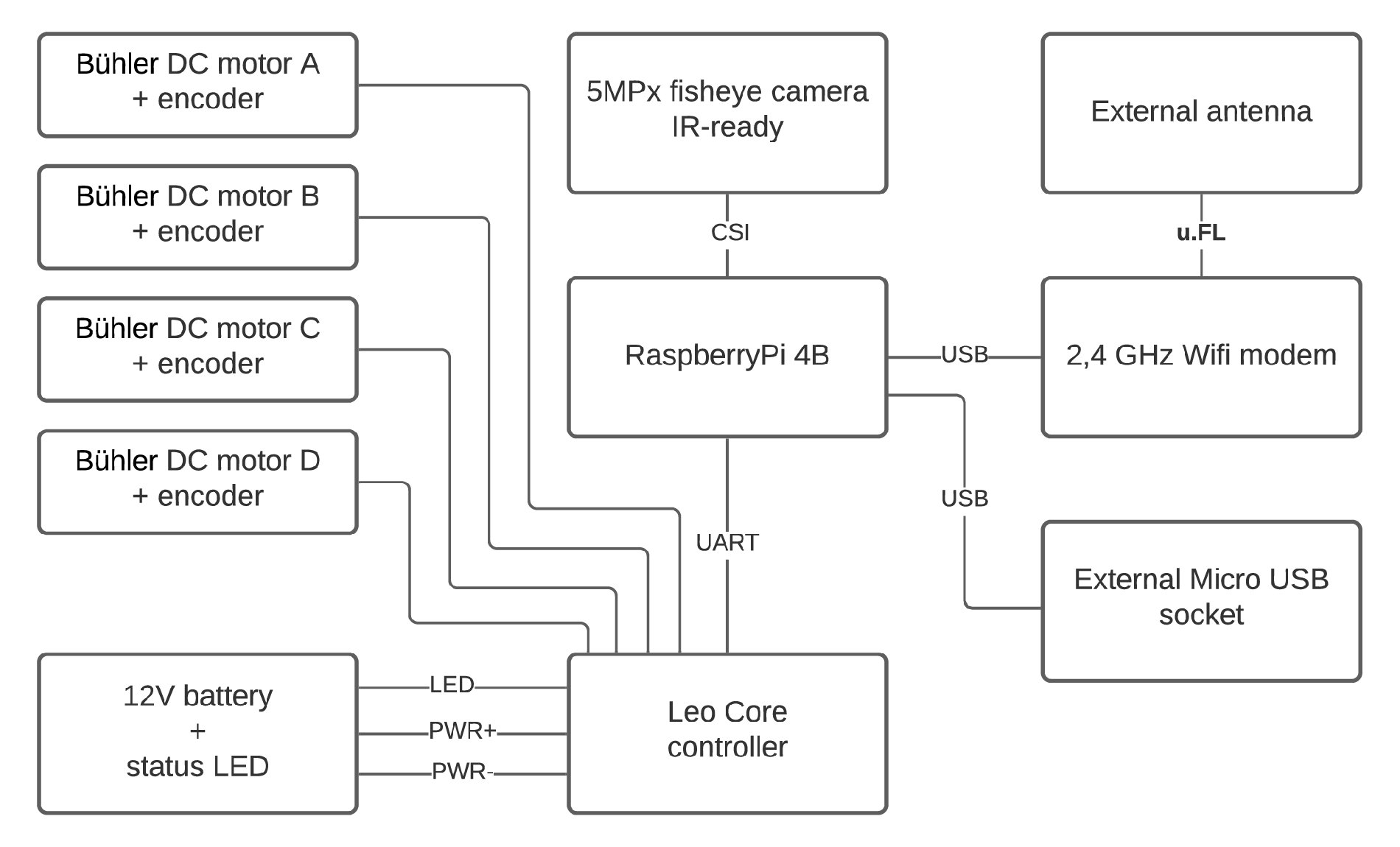
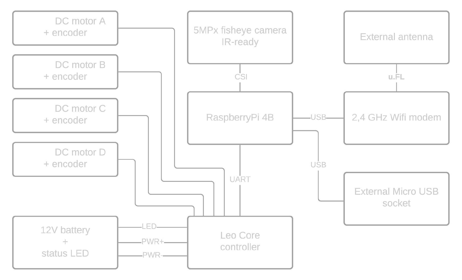
LeoCore controller
LeoCore is the main control board of the Leo Rover platform, responsible for power distribution, motor control, and communication with the onboard Raspberry Pi computer. Equipped with an STM32F401 microcontroller, it provides robust protection, precise motor drivers, and expandable I/O ports - making it a reliable foundation for robotics research, education, and prototyping.
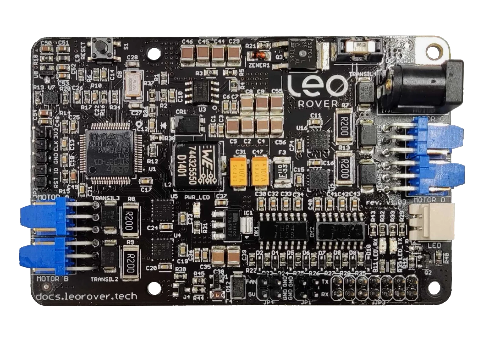
General
- Custom LeoCore board with STM32F401 microcontroller
- Works with Raspberry Pi (power + UART serial communication)
- Provides power and serial communication between LeoCore and Raspberry Pi
- Manages system readiness indicator (battery LED)
- Total current draw from all 5V outputs must not exceed 5A
- Operating temperature: -20°C to +50°C
|
| Port | Functionality |
|---|---|
| Power Input |
|
| Motor Outputs |
|
| LED Output |
|
| Fan Connector |
|
| GPIO Port |
|
| UART Port |
|
| Debug Port |
|
Take into consideration during the Rover assembly and development. The board corner where there's power connector and power-related components tends to interfere with sensitive electronics such as wheel encoders. Make sure the encoder cables don't run on top of the corner.
3-pin power connector pinout
By default Leo Rover uses standard WEIPU SP13-3 connectors for connecting battery, Main Electronics Box and other possible addons.


| Pin name | Cable color |
|---|---|
| DC- | black |
| DC+ | red / black with white stripe |
| LED | green |
Software structure
- LeoOS 1.x
- LeoOS 2.x


Leo Rover's software heavily relies on the Robot Operating System (ROS), which offers the robot the following functionalities:
- Abstraction layer facilitating communication between software components.
- Open-source software components, maintained by the community.
- A collection of standard message interfaces.
- Tools for introspection.
The primary segment of the software stack consists of several ROS Nodes, which are computational units, each performing a single logical function. The nodes interact via:
- Topics - Named buses enabling message exchange between nodes. They are strongly typed and employ anonymous publish/subscribe semantics.
- Services - A client/server mechanism for remote procedure calls between nodes. The service server accepts remote procedure requests identified by name and type, which must be known to the service client beforehand.
- Parameters - Sets of key/value pairs maintained separately by each node, utilized for node configuration during startup and runtime without necessitating code modifications.
- TF transforms - A single transform describes the relationship between two coordinate frames at a specific point in time. TF transforms are distributed between nodes using topics, but, for the sake of clarity, we will refer to them as separate entities.
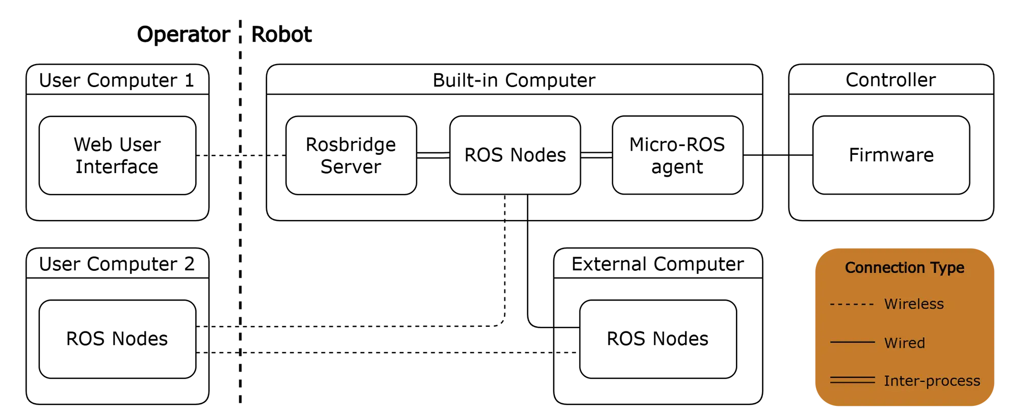
There are two important software components that don't run as native ROS nodes:
- Controller firmware - The firmware itself acts as a ROS node, but uses eProsima's Micro XRCE-DDS as its middleware. Therefore, it requires the presence of the Micro-ROS Agent on the built-in computer to communicate with other ROS nodes.
- Web User Interface - The WebUI establishes a connection with the Rosbridge Server via the WebSocket transport layer and employs the Rosbridge protocol for communication with ROS nodes.
Operating system
Ready-to-go UI located under 10.0.0.1 when using standard Leo Software Image.
Firmware
This is the program that runs directly on the processor of the LeoCore board. It provides different functionalities to the Raspberry Pi through serial bus. The main features of the default leocore_firmware are:
- differential drive controller (cmd_vel interface)
- wheel states monitoring (joint_states interface)
- battery voltage monitoring
- wheel odometry calculation
- IMU support
The "Firmware" refers to the low-level software running on the LeoCore controller. It utilizes Micro-ROS to communicate with the built-in computer via the Micro XRCE-DDS protocol and exposes functionalities such as:
- velocity commands for the robot,
- velocity and PWM commands for individual wheels,
- battery voltage feedback,
- wheel states (position, velocity, torque, PWM duty) feedback,
- odometry feedback (calculated from wheel encoders),
- feedback from the IMU sensor.
ROS nodes
When the Raspberry Pi boots, a set of ROS nodes is started. These nodes allow different features to be accessed via ROS topics and services. They are defined in leo_bringup package and mainly consist of:
- rosserial node - communicates with the firmware via serial interface and makes its features available via ROS topics and services
- Rosbridge server - creates WebSocket that provides a JSON API to ROS functionality for non-ROS programs.
- Raspicam node - publishes images from Raspberry Pi camera module to ROS image transport topic
- Web video server - provides a video stream of a ROS image transport topic that can be accessed via HTTP
- Leo system node - provides system shutdown and reboot via ROS topics.
| ROS Node | Description |
|---|---|
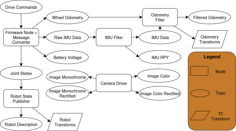
| Firmware Node | The node spawned by the LeoCore controller firmware. Allows control of the robot's wheels via topics. Additionally, it publishes relevant information, including:
|
| Robot State Publisher | Parses the kinematic tree model of the robot in URDF format and broadcasts the robot state using TF transforms. Here's how it operates:
It also publishes the robot URDF description on a designated topic, making it easily accessible to other nodes. |
| Camera Driver | Publishes camera information and various camera images, including:
All images are published at 15 FPS, both in their original resolution and in compressed versions. |
| Firmware Message Converter | Converts messages from the Firmware Node to standard ROS messages. |
| IMU Filter | Processes raw IMU data using a complementary filter which:
The gyroscope bias is periodically saved to persistent storage and loaded on startup. The node also enables calibration reset via a service. |
| Odometry Filter | Fuses wheel odometry and filtered IMU data to compute the robot's pose and velocity, and publishes this information. It can optionally broadcast an odometry TF transform and supports resetting the odometry via a service. |
| Web Video Server | Provides HTTP video streaming of ROS image topics to the Web User Interface. |
| Rosbridge Server | Provides a WebSocket interface to the ROS system, allowing the Web User Interface to communicate with ROS nodes. |
The names of nodes, topics, services are simplified for clarity.
Web user interface (UI)
This is the user interface that can be accessed via a web browser. It communicates with Rosbridge server using roslibjs to access functionalities that are available in ROS topics. The default leo_ui brings features such as:
- control of the Rover via a keyboard or a virtual joystick
- display of a camera stream from Web video server
- output of current battery voltage measurement
- reboot and shutdown buttons