UBlox EVK-M8N GPS Integration
This tutorial will guide you through the process of connecting a UBlox GPS module to your Leo Rover.
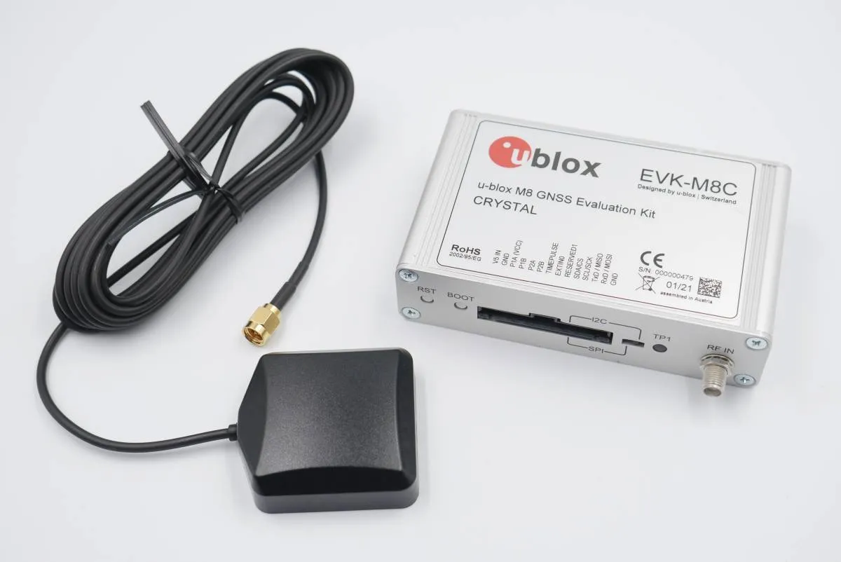
EVK-7 / EVK-8 / EVK-M8 evaluation kits make evaluating the high performance u-blox 7, u-blox 8 and u-blox M8 positioning products simple. The built-in USB interface provides both power supply and high-speed data transfer, and eliminates the need for an external power supply. The u-blox evaluation kits are compact, and their user-friendly interface and power supply make them ideally suited for use in laboratories, vehicles and outdoor locations.
In this tutorial we will present the process of connecting a UBlox GPS module to your Leo Rover and integrating it with the system on the UBlox EVK-M8N GPS module example.
The steps might slightly differ for other UBlox models, but should be essentially similar.
What to expect?
After completing this tutorial, you should be able to gather the GPS data and get it published on ROS topics.
Prerequisites
Referenced products
List of components
- UBlox GPS module (we have used the UBlox EVK-M8N GPS module)
- Any computer which you can connect to the rover via ssh.
Mechanical integration
When it comes to mounting the module, any solution that works for you is okay. You can 3D print a special mounting plate, use a velcro or even a tape.
Wiring and electronics connection
Wiring up the module is very simple, as it doesn't require external power supply. You just need to connect the module with a USB cable with the rover via the USB socket in the mounting plate. There is a micro-usb mounting hole with the USB sign on the module, and you need to plug in the USB cable there.
Software integration
The first thing you can do is to make sure your device has the correct permissions and is available at the fixed path on your system.
We will need USB Vendor and Product IDs to make the rules for the correct
device. To get that information, you need to connect to the rover via ssh, and
then, you can use the lsusb command. It will list all connected usb devices.
In the output, you should look for something named like U-Blox AG [u-blox
8]:
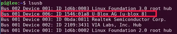
Now, our Vendor and Product IDs are the two strings after "ID" divided by colon.
In our case, idVendor is 1546 and idProduct is 01a8.
Now, you need to make a udev rules file.
ATTRS{idVendor}=="1546", ATTRS{idProduct}=="01a8", MODE="0666", GROUP="dialout", SYMLINK+="ublox_gps"
Paste these lines to /etc/udev/rules.d/ublox.rules file and reload udev
rules by typing:
sudo udevadm control --reload-rules && sudo udevadm trigger
Your device should now be available at the /dev/ublox_gps path.
We want the sensor functionality to be available in the ROS ecosystem, so you should install a ROS package that provides a node for the sensor you are trying to integrate.
sudo apt install ros-${ROS_DISTRO}-ublox
Now, create a launch file that would start the node with a fitting configuration.
<launch>
  <node pkg="ublox_gps" exec="ublox_gps_node" output="screen">
    <param from="$(find-pkg-share ublox_gps)/config/c94_m8p_rover.yaml" />
    <param name="device" value="/dev/ublox_gps"/>
    <param name="frame_id" value="ublox_frame"/>
  </node>
</launch>
In /etc/ros/robot.launch.xml add this line somewhere before the closing
</launch> tag, so that your node will start at boot.
<include file="/etc/ros/gps.launch.xml"/>
Your robot should be aware of where the module is located and what space it occupies. You can ensure it does that by creating a URDF model of the module.
<?xml version="1.0"?>
<robot>
  <link name="ublox_frame"/>

  <joint name="ublox_joint" type="fixed">
    <origin xyz="-0.05 0 0"/>
    <parent link="base_link"/>
    <child link="ublox_frame"/>
  </joint>

</robot>
Make sure that frame_id param in the launch file and link name in
ublox.urdf file have the same value.
And including it in the description that is uploaded at boot. Add this line
somewhere before the closing </robot> tag.
<xacro:include filename="/etc/ros/urdf/ublox.urdf"/>
The last step is to restart the nodes
ros-nodes-restart
Examples
Checking the GPS module accuracy
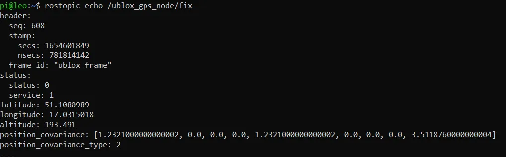
Type this command into the console to check the data sent by GPS module:
ros2 topic echo /fix
You should see a lot of data flowing through the topic. Stop the data acquisition with Ctrl+C and have a look on a usual data frame.
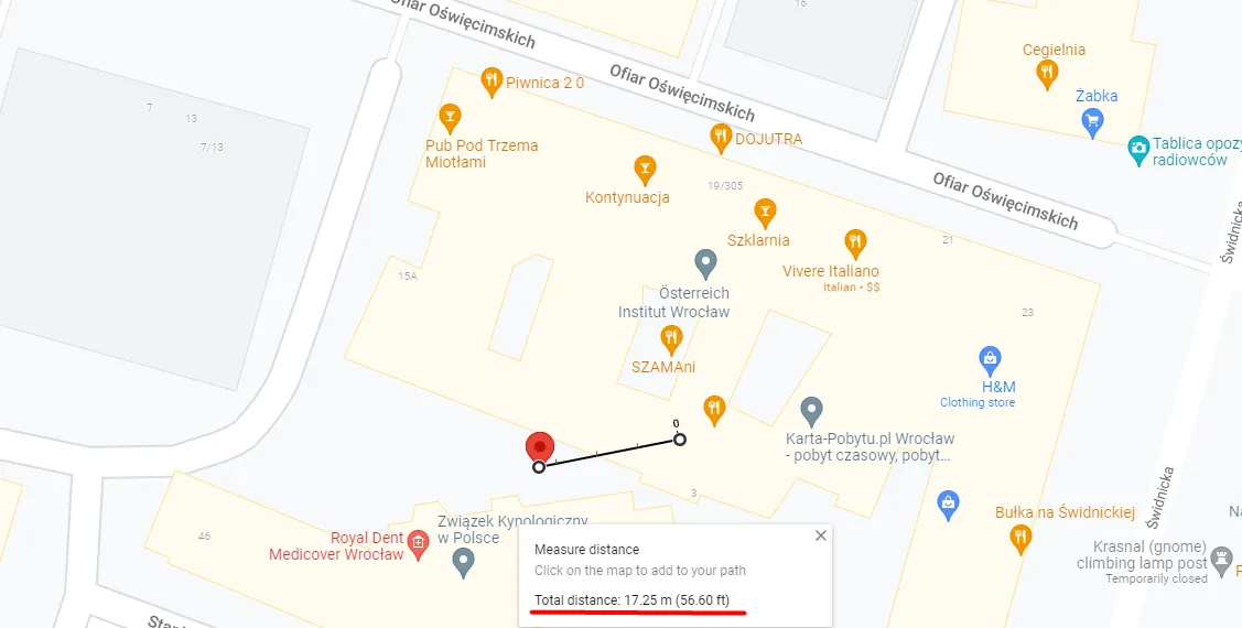
Using Google Maps you can easily evaluate the precision of your GPS module. Find the latitude and longitude data in the data frames send by the module. Copy and paste it into google maps search bar. When a pin appears, you should be able to see where the module thinks it is.
Usually accuracy is off by some factor. Depending on the amount of interferences and the quality of the GPS module, the difference between real location and the position gathered with GPS module may vary.
Right click on the map location you believe you are at and use "Measure distance" option at the bottom of the list. Then, create another spot for the distance measuring tool right where the red marker is. Google will then do the math and show you the distance between your real location and where the GPS module thinks it is.
What next?
GPS modules are commonly used in projects involving outside autonomous navigation. As of right now, we have no tutorials on such a thing, however, our tutorial on indoor autonomous navigation you might be something you'll be interested in.
You can also check our Integrations page for other instructions.