Trossen Robotics PincherX 100 mobile
In this tutorial, we will show you how to configure and remotely control Trossen Robotics' PhantomX PincherX 100 mobile connected to Leo Rover.
PincherX 100 Mobile, with its 4DOF and 300mm reach, is on the smaller side of robotic arms, however, it's big enough to be used as a nice extension for a Leo Rover. The following tutorial outlines the basics of how to connect it to the rover and shows how some ROS packages might be used with it. Robotic arms are used anywhere from education and factories up to dangerous materials handling facilities, that's why a range of possibilities emerging from attaching a robotic arm to the rover is almost endless. We hope that this tutorial will be a good starting point to use robotic arms in your future projects.
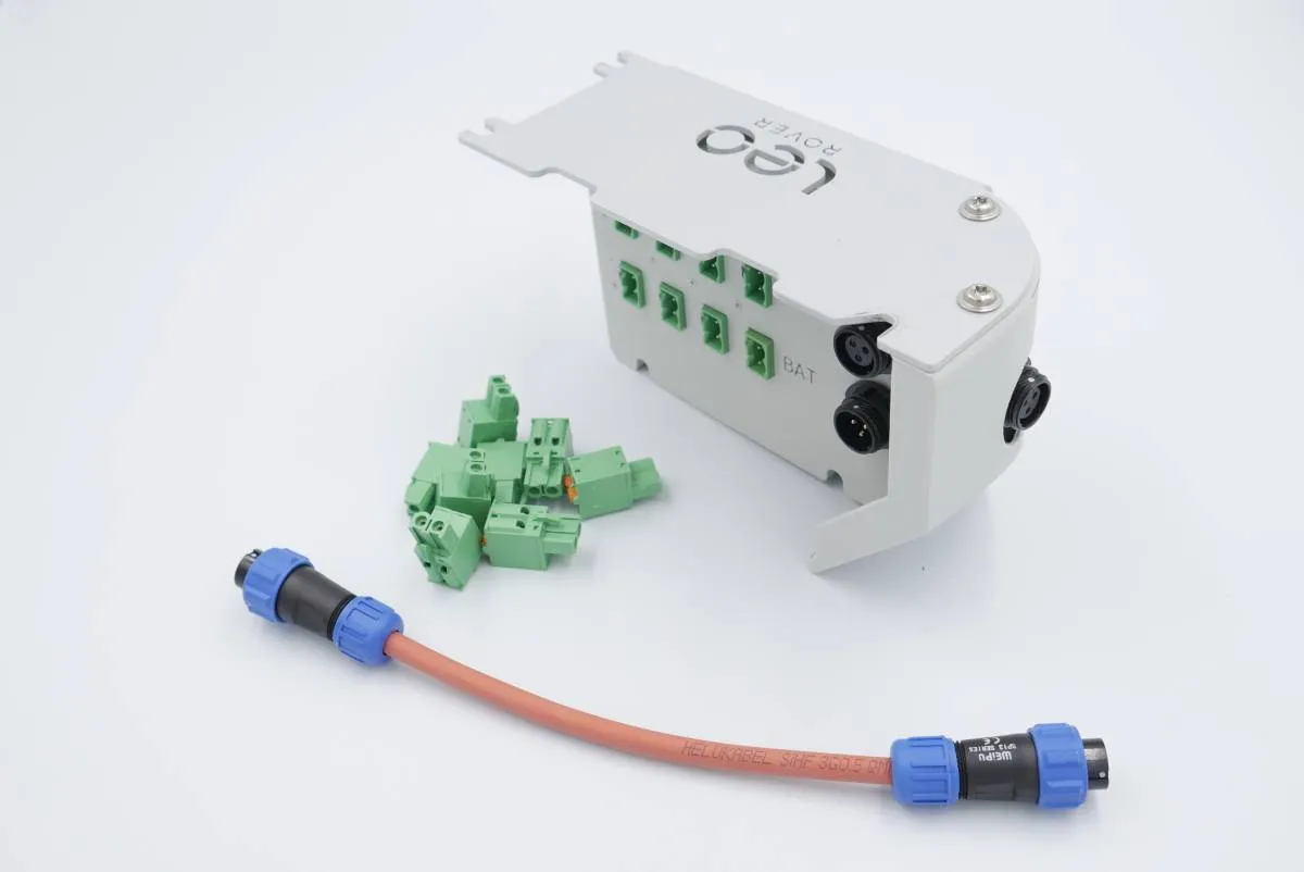
To make integration easier we highly recommend to make use of Powerbox addon
What to expect?
This tutorial will teach you how to connect PincherX 100 Mobile to a Leo Rover, visualize it using RViz and the basics of control using MoveIt, joystick, and command line.
Prerequisites
Referenced products
List of components
- PincherX 100 Mobile robotic arm
- M5x10 Allen head screw x 4
- M3x6 Allen head screw x 4
- Barrel Jack cable (connected to ~12V power supply - e.g. rovers battery)
Mechanical integration
We've redesigned the base of the arm in order to make it easier to connect it to the rover.

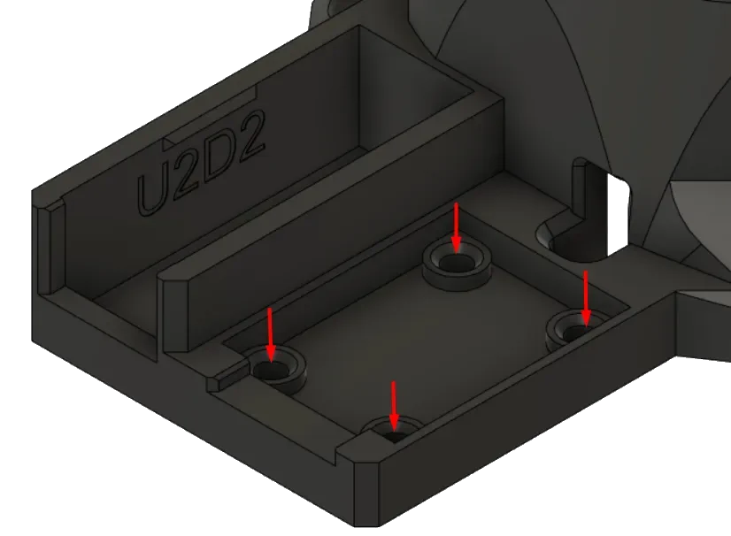
If you want to print it on your own, you can find the STL file here. After printing, it you'll need to press 4x M3 heat set inserts into the holes shown below.
To replace the stock base with the one you printed, you need to remove all the screws at the bottom of the arm, gently lift old cover and switch it for a new one. Remember to stick the Dynamixel cable through the hole in the base. Then, screw the screws back in place.
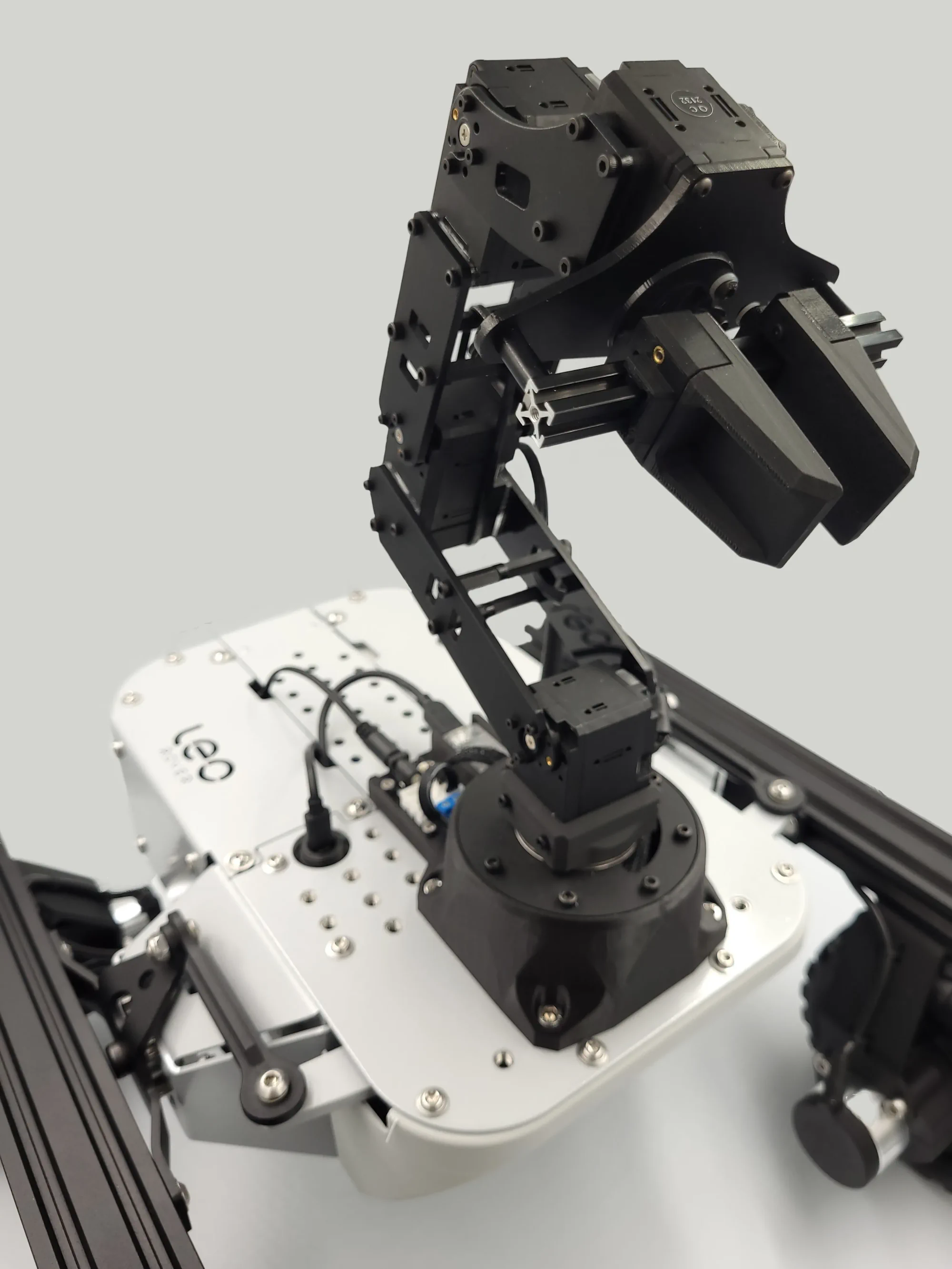
Use 4x M5x10 allen head screws to bolt the arm to the mounting plate of the Leo Rover.
Press U2D2 into the deeper opening; it's going to snap in place and will be held securely inside.
Using 4x M3x6 allen head screws, bolt the power/communication distribution board to the base.
If you've bought the arm from our online shop, it will come with the base already replaced.
Wiring and electronics connection
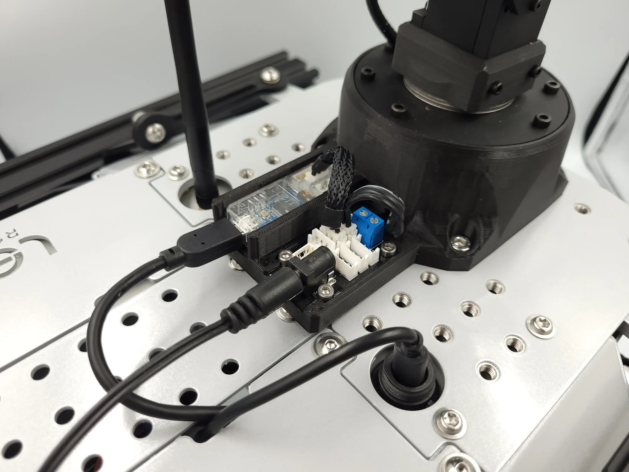
Stick the Dynamixel cable coming out of the base of the arm into the power distribution board.
Connect U2D2 and the power distribution board with the short Dynamixel cable.
Connect the U2D2 to the rover using an USB cable
The last step is to stick connect the barrel jack cable to the battery power supply (Powerbox addon might be useful here) and plug into the other end into power distribution board.
With everything connected it should look like this:
Software integration
As the installation process of the arm's ROS packages might be difficult, we have prepared bash script that will guide you through the installation. To execute it, you need to connect to the rover via ssh (see prerequisites), and type in the terminal on the rover:
bash <(wget -O- http://files.fictionlab.pl/utilities/install_interbotix_packages.sh); rm wget-log
You will be asked to provide the absolute path to your ROS workspace (if you don't have one on the rover, check this tutorial first). Type it in and confirm with enter.
Don't worry if you make a typo. After providing the path you will have an opportunity to check it and correct possible mistakes - there will be a prompt asking if everything is correct.
The installation process might take a while (up to 20 minutes), so be patient.
Once the packages have been built, you can edit the environmental setup file to
point to your result space. Open the file in nano:
nano /etc/ros/setup.bash
Comment out the first line by adding the # sign and add the source command for
your workspace. The first 2 lines should look essentially like this:
# source /opt/ros/melodic/setup.bash
source /home/pi/ros_ws/devel/setup.bash
Different operations on the arm require different modes for the ros_controller. Instead of changing the package configs, we will make our own config file, and load it in the launch file. First, make your config file and open it to edit it:
touch /etc/ros/arm_modes.yaml
nano /etc/ros/arm_modes.yaml
Then, paste these lines in the file (ctrl+shift+V):
groups:
  arm:
    operating_mode: position
    profile_type: time
    profile_velocity: 131
    profile_acceleration: 25
    torque_enable: true

singles:
  gripper:
    operating_mode: pwm
    profile_type: velocity
    profile_velocity: 131
    profile_acceleration: 15
    torque_enable: true
To save and exit the file, you can use respectively ctrl+O and ctrl+X.
Now, to add the arm's driver to the rover's launch file, open the robot.launch
file:
nano /etc/ros/robot.launch
and paste these lines somewhere between the <launch> tags:
<include file="$(find interbotix_xsarm_ros_control)/launch/xsarm_ros_control.launch">
    <arg name="robot_model" value="mobile_px100" />
    <arg name="dof" value="4" />
    <arg name="use_world_frame" value="false" />
    <arg name="mode_configs" value="/etc/ros/arm_modes.yaml" />
</include>
You can also edit the robot's URDF file to connect the arm's base link to the
rover's model. To do this, open the robot.urdf.xacro file:
nano /etc/ros/urdf/robot.urdf.xacro
and paste these lines somewhere between the <robot> tags:
<link name="mobile_px100/base_link"/>

<joint name="arm_joint" type="fixed">
  <origin xyz="0.043 0 -0.001"/>
  <parent link="base_link"/>
  <child link="mobile_px100/base_link"/>
</joint>
To learn more about what the files under /etc/ros are used for and how do they correlate with each other, visit the Adding additional functionality to the rover section on ROS Development guide:
That's it! On the next boot, the arm driver node will start together with all the other nodes. You can manually restart the running nodes by typing:
sudo systemctl restart leo
Examples
Controlling the arm
Now that you have the driver running, you should see the new ROS topics and
services under the /mobile_px100 namespace. For a full description of the ROS
API, visit the
ROS controllers configuration README page.
You can test some of the features with the rostopic and rosservice
command-line tools:
Retrieve the information about the arm (all joints):
rosservice call /mobile_px100/get_robot_info "{cmd_type: 'group', name: 'all'}"
Publish the position command to the elbow joint:
rostopic pub /mobile_px100/commands/joint_single interbotix_xs_msgs/JointSingleCommand "{name: 'elbow', cmd: 0.0}"
Turn off the torque on all joints:
rosservice call /mobile_px100/torque_enable "{cmd_type: 'group', name: 'all', enable: false}"
There are other ways to control the arm, but it's better to use them on your computer and not the rover. To do so, you need to install the ROS packages on your computer (you can use the same command that you have used for installing the packages on the rover), but you need to have a computer with ROS installed (see prerequisites), ROS workspace and Linux OS.
You also need your computer to be properly configured to communicate with the nodes running on the rover. For this, you can visit the Connecting other computer to ROS network section of the ROS Development tutorial:
It's also useful to have the leo_description package installed on your
computer for visualization purposes. To install it, type:
sudo apt install ros-noetic-leo-description
Visualizing the model
- Open RViz by typing
rvizin the terminal. - Choose
base_linkas the Fixed Frame
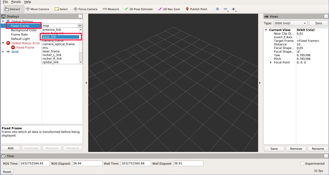
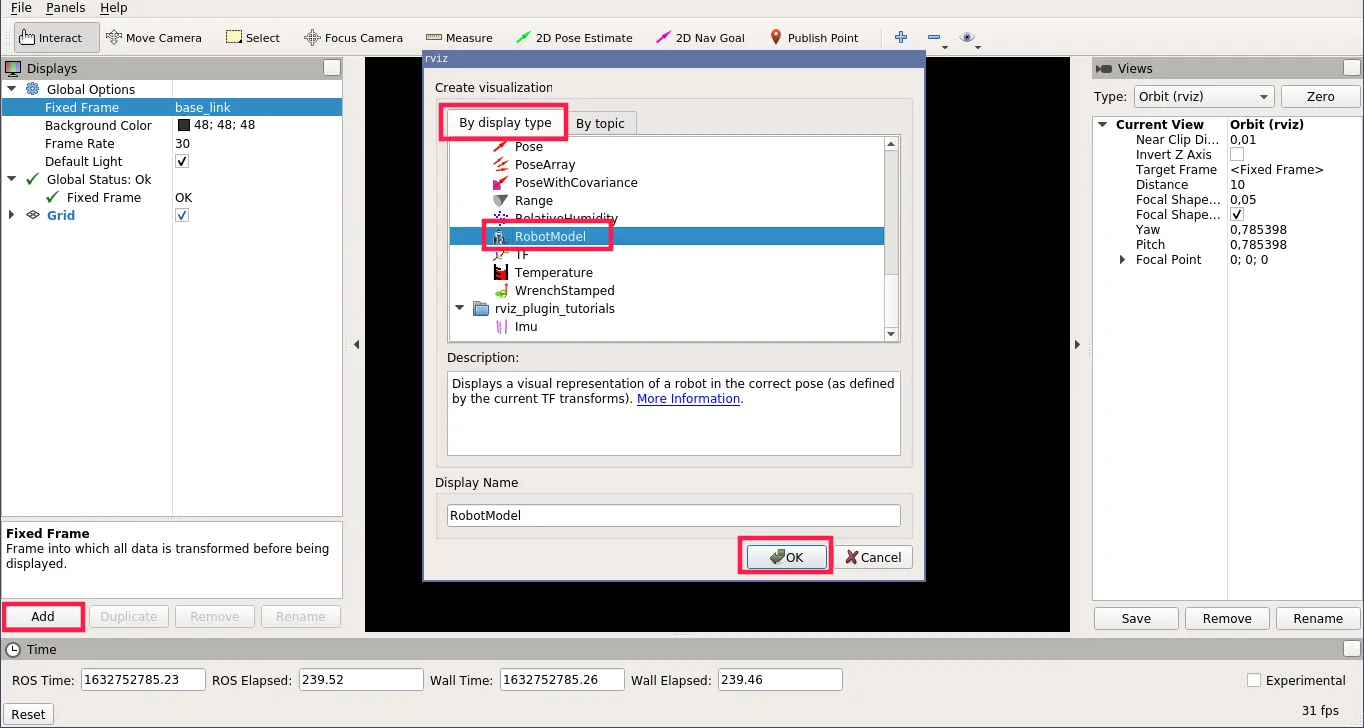
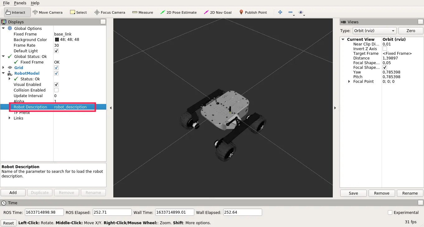
- On the Displays panel, click on Add and choose RobotModel.
- For the Robot Description parameter, choose
robot_description.
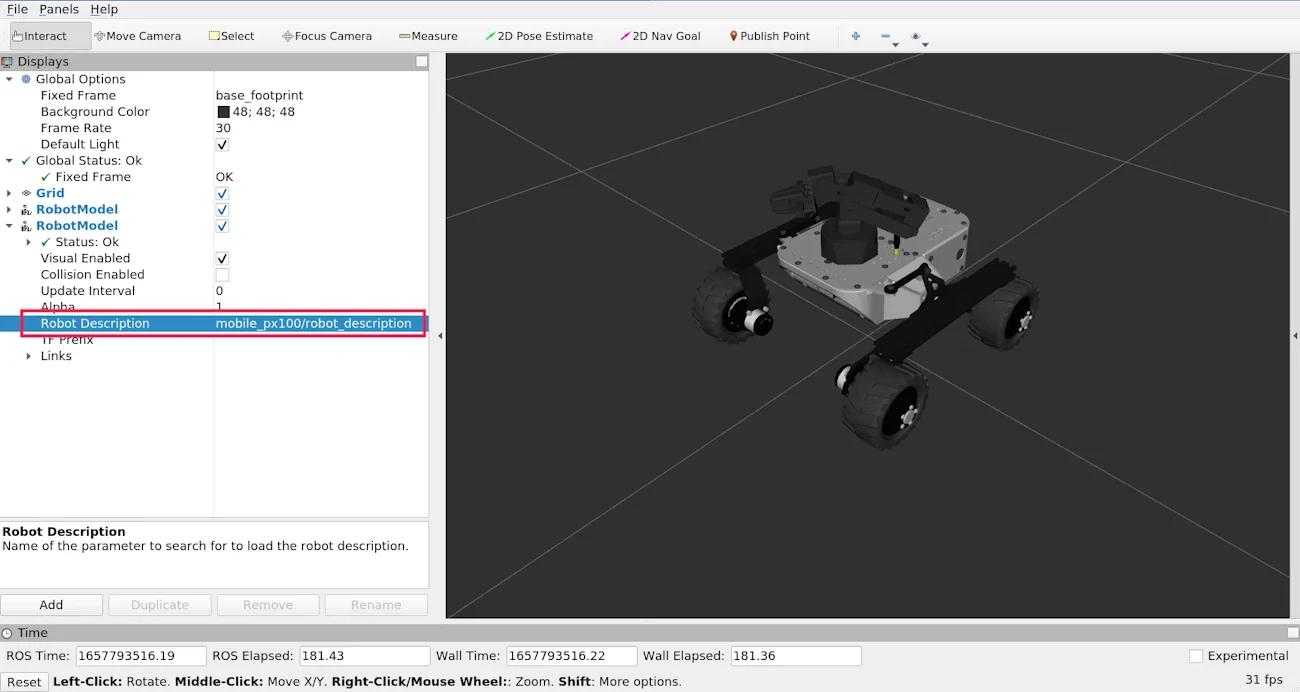
Add another RobotModel display, but for the Robot Description parameter
choose mobile_px100/robot_description.
Planning the trajectory with MoveIt
MoveIt motion planning framework will allow us to plan and execute a
collision-free trajectory to the destination pose of the end-effector. To use
it, first, make sure that the arm is powered and connected to the rover and that
the ros_control node is running on the rover. You can check it with:
sudo systemctl status leo
and check logs for the nodes in the /mobile_px100 namespace. You can also
check the list of running nodes using:
rosnode list
And check if there are nodes in the same namespace listed.
Once you are sure the nodes are running, you can go to your computer and run the MoveIt. But first, you need to connect your computer to the rover's ROS network (tutorial linked in previous example). You can check if your computer is connected with:
rostopic list
If the computer is correctly connected, you will see the list of the topics that are currently available in the ROS network (all of them are on the rover if you don't have any node launched on your computer).
To work correctly with the arm, MoveIt requires us to change the loaded arm
mode. We need to load back the default mode. To do so, first, open to the
robot.launch file (on the rover):
nano /etc/ros/robot.launch
And comment the line where we specify the path for our mode (replace the line in the file with the line below):
<!-- <arg name="mode_configs" value="/etc/ros/arm_modes.yaml" /> -->
Now, you just need to restart the running nodes with:
sudo systemctl restart leo
To run MoveIt with the PincherX 100 Mobile arm, run on your computer:
roslaunch interbotix_xsarm_moveit xsarm_moveit.launch robot_model:=mobile_px100 use_actual:=false dof:=4 rviz_frame:=base_link use_world_frame:=false
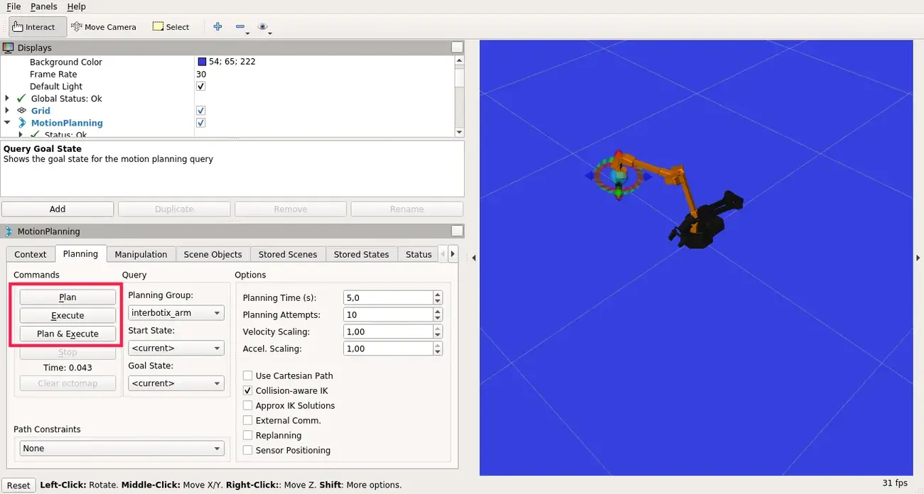
The MoveIt GUI should appear:
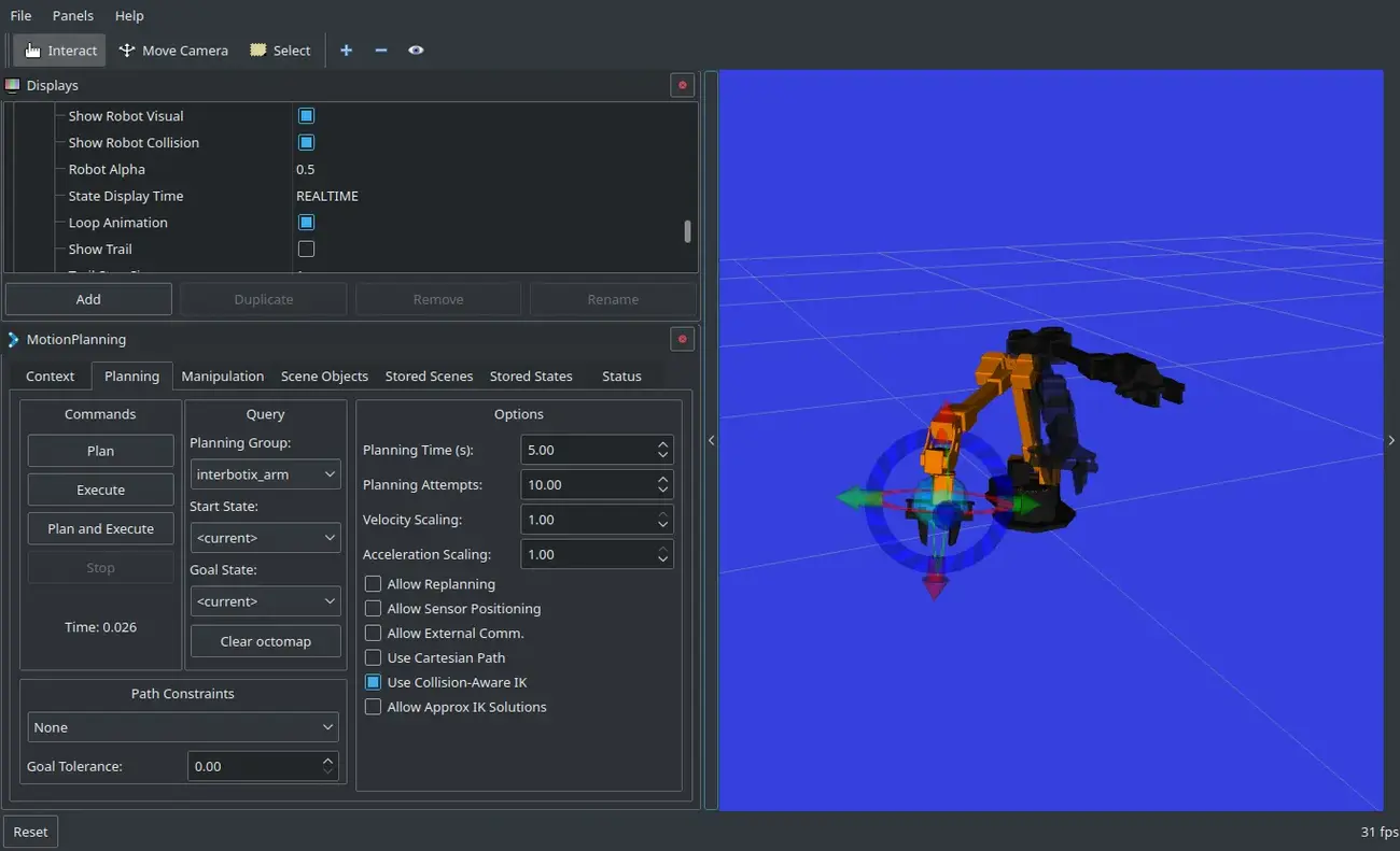
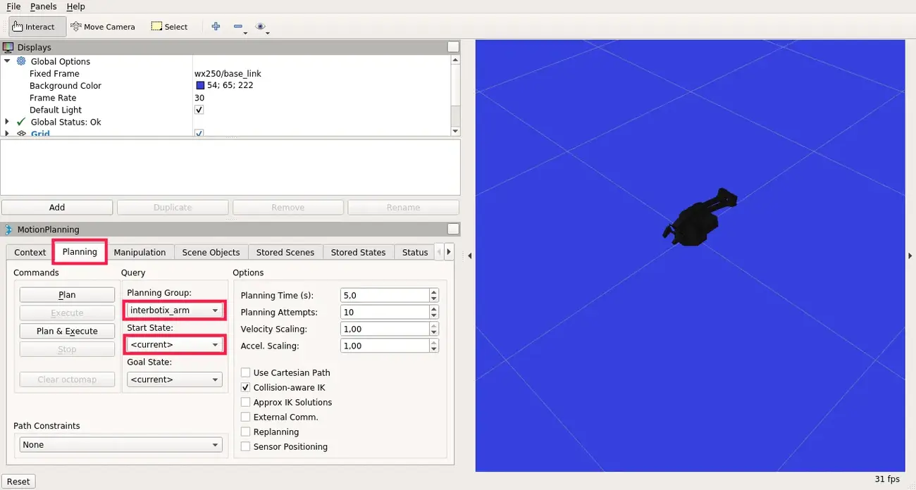
On the MotionPlanning panel, click on the Planning tab, choose
interbotix_arm for the Planning Group and <current> for the Start
State (to operate with the gripper, change the Planning Group to
interbotix_gripper)
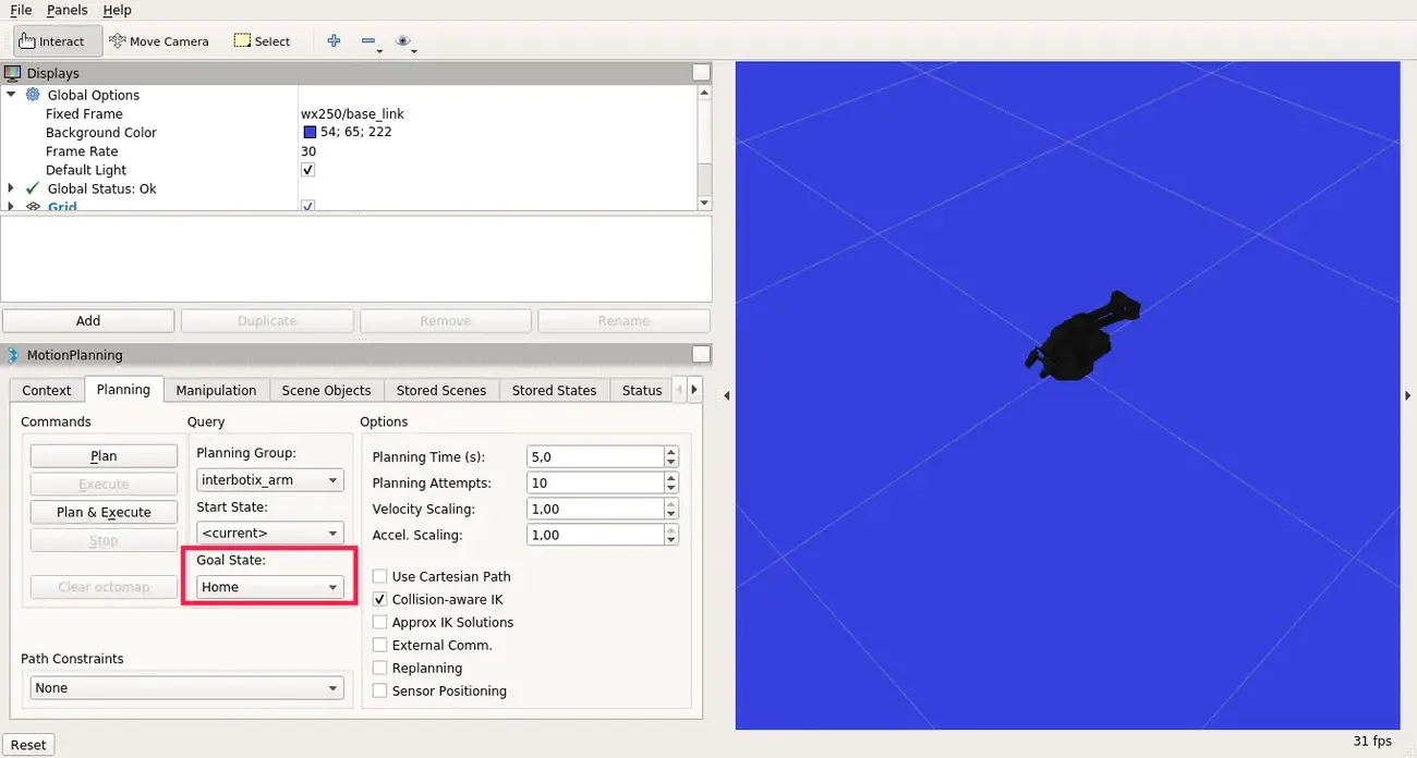
There are some predefined poses which you can choose for the Goal State,
such as home, sleep or upright (for the gripper, the poses are open,
closed, home).
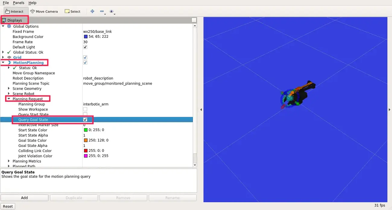
To set the pose manually, navigate to the Displays panel ->
MotionPlanning -> Planning Request and check Query Goal State. You
should now be able to manually set the end-effector pose for the goal state
(only for the whole arm, for the gripper it won't work).
When the goal state is set, click on the Plan button to plan the trajectory (the simulated trajectory visualization should appear) and Execute to send the trajectory to the driver.
If you want to use the MoveIt capabilities in a Python script or a C++ program, please look at the interbotix_moveit_interface example.
Using joystick to control the arm
The interbotix_xsarm_joy package provides the capability to control the
movement of the arm (utilizing inverse kinematics) with a PS3, PS4 or an Xbox
360 joystick.
To use the package with the arm connected to your rover:
- Connect the joystick to your computer.
- Start the
joy_control.launchfile:
roslaunch interbotix_xsarm_joy xsarm_joy.launch launch_driver:=false robot_model:=mobile_px100 controller:=ps
- Change controller to either
ps3,ps4orxbox360depending on the joystick you have connected.
For operating instructions see the Joystick Control README page.
Using the Python API
Aside from the previous examples, there is also a Python API for manipulating
the arm. It is designed to mainly work with the position mode for the arm,
pwm mode for the gripper and the Time-Based-Profile (these are the default
configs in the interbotix_xsarm_control package).
There are some example scripts that demonstrate the use of the API in the
interbotix_ros_manipulators/interbotix_ros_xsarms/examples/python_demos
directory.
cd <path_to_your_ros_workspace>/src/interbotix_ros_manipulators/interbotix_ros_xsarms/examples/python_demos
The bartender.py demo performs some pick, pour and place operations. To run
it, first, open the file in a text editor and search for this line:
bot = InterbotixManipulatorXS("wx250s", "arm", "gripper")
Change wx250s to mobile_px100 and then, type on the terminal:
python bartender.py
Make sure that you are not running any other script that takes control of the arm simultaneously (e.g. the joy control node).
If everything went right, you should see the arm in action.
You can check the other files in the directory for more examples. To get a better understanding on how the API can be used and the API documentation, take a look at interbotix_xs_modules.
What next?
If you found this tutorial interesting, make sure to check out other tutorials we provide on our Integrations site.