Arduino boards
In this tutorial, we'll show you how to connect Arduino to Leo Rover.
What is Arduino?
Before we get started, let's say a few words about what Arduino actually is.
Arduino is an open-source electronic platform that allows users to easily access advanced technologies interacting with the physical world.
What do I need Arduino for?
You might wonder what the point of having Arduino inside Leo Rover is. After all, isn't the robot already equipped with a Raspberry Pi micro-computer?
Well, the simplicity of Arduino makes it more convenient for typical hardware projects. Arduino has analog capabilities that the Raspberry Pi lacks by default. Its flexibility allows you to work with almost any type of sensor.
Arduino speeds up the creation of simple projects that don't require advanced software and a good Internet connection.
Let's not forget that behind the name "Arduino" hide many boards, so if you want to learn how to choose the best one for your project, look here. For our projects, we mostly use Arduino DUE.
What to expect?
Having finished the tutorial you'll know how to connect Arduino to the Leo Rover and use its potential to further improve your projects and make the development process of future projects a little bit faster.
Prerequisites
List of components
- Any Arduino ( or any other compatible board)
- Any way of connecting the board to the rover
- USB cable
Mechanical integration
We have created mechanical interfaces for Arduino DUE, which you can get here:
You'll need to press in ten M3, threaded heat-set inserts into the base part. This allows you to use M3x6 Allen screws to hold the Arduino securely. The cover is held by 4 screws of the same size.
Since Arduino Due has the largest footprint out of all the Arduino boards it should be pretty easy to adapt the provided Arduino DUE adapter models to fit other boards inside. All you need to do is use 3D CAD program like Autodesk Fusion to change the way mounting holes for the board are positioned.
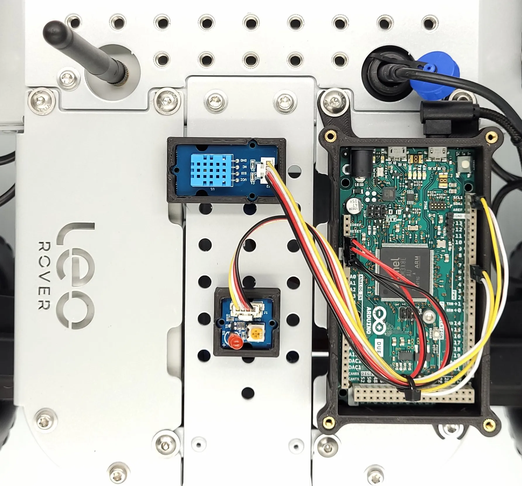
Wiring and electronics connection
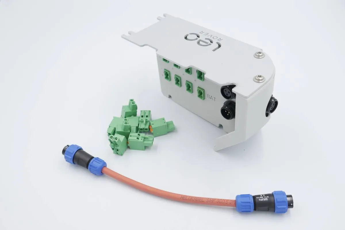
For most intents and purposes the only connection you need to provide is an USB connection between the board and the USB port at the top of the rover. However, you may want to provide the microcontroller, and the sensors that you are using, with external power source. For such cases powerbox addon might be a good choice.
Software integration
There are several ways to integrate Arduino into the rover. From this tutorial, you'll learn about two of them so that you can decide which one works best for you.
- Mechanical engineer way
- Software engineer way
This way saves you from having to dive into the rover's insides. It works; however, it does not allow you to communicate between the rover's onboard computer and Arduino - this, in turn, makes it harder to use the data harvested by any sensors connected to the Arduino.
First, install Arduino IDE using any of those provided tutorials:
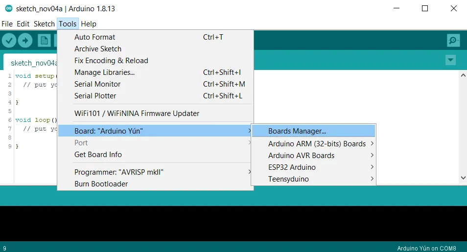
Then, you need to set up Arduino IDE (we're using Arduino DUE which needs a special configuration in Arduino IDE).
To do so, do as follows: while in IDE, go to: Tools -> Board -> Boards Manager
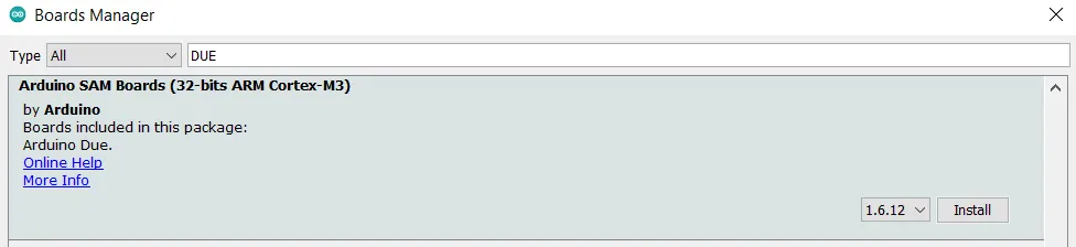
Type DUE in the search bar and install the latest version of
Arduino SAM Boards (32-bits ARM Cortex-M3).
The next step is to take care of the board specific setup:
- Connect the board to a USB port in your computer (use the port closer to the barrel jack socket)
- Go to: Tools -> Board -> Arduino ARM (32-bits) Boards and choose Arduino Due (Programming Port)
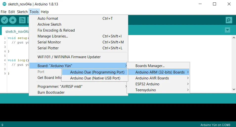
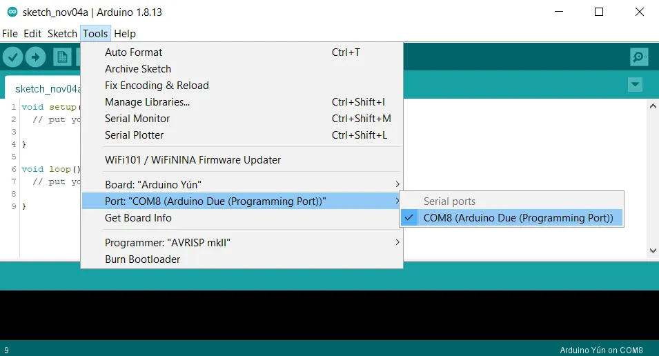
- Go to: Tools -> Port and choose the port Arduino is connected to
This way allows you to communicate between the rover's onboard computer and the Arduino board. However, it takes a bit longer to set up than the previous method.
Following the steps below gives you the ability to use Arduino IDE and programming the boards directly from the Leo Rover's on-board computer. This means that you won't have to disconnect the board from your computer and connect it to the Leo Rover every time you make a small change in the code. However, it comes with a drawback of using a less powerful computer to write the code at.
If reconnecting the Arduino between your computer and Leo Rover every time you make a change to the code is not a problem to you follow The mechanical engineer way and then skip to Setting up the Rosserial communication.
First connect to the rover via Remote Desktop and connect the rover to the network (see Prerequisites).
Now, install and set up Arduino IDE following instructions below:
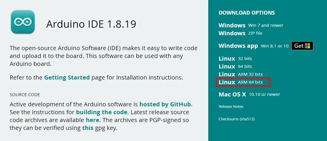
Visit this website and download the latest
version of Arduino IDE. Make sure to get the Linux ARM 64 bits version.
Now, you need to extract the .tar file. To do so open new terminal
(ctrl+alt+T) and go to the downloads directory, and unpack the Arduino
installation files with tar command.
cd ~/Downloads
tar -xf arduino-<version>-linuxarm.tar.xz
Unpacking might take a while, just wait until it's completed.
Also make note of what Arduino IDE version you are installing as it might be
different. If you are not sure, what is your file, check the files while being
in Downloads directory with ls command.
You can see the unpacked files in the directory using ls command.

Now you need to move extracted files from Downloads directory, to /opt
directory. To do so type (while being in Downloads directory):
sudo mv arduino-<Version> /opt
When you are using sudo you might get asked for root password. Just type it in, and confirm with Enter.
Then you need to install the files. To do so go to the moved Arduino files in
/opt directory and run install.sh script.
Once again pay attention to your Arduino files version, so you go to the correct
directory. You may also need to give execution rights to install.sh script. To
do so type:
sudo chmod +x install.sh
Arduino IDE should be installed and you should see new icon on the Desktop.
Now, connect Arduino to the rover. To do so, plug the USB cable in and then, open the Arduino IDE.
After that, set up the board specific options doing the following steps:
While in IDE, go to: Tools -> Board -> Boards Manager
Type DUE in the search bar and install the latest version of
Arduino SAM Boards (32-bits ARM Cortex-M3).
The next step is to take care of the board specific setup:
- Connect the board to a USB port in your computer (use the port closer to the barrel jack socket)
- Go to: Tools -> Board -> Arduino ARM (32-bits) Boards and choose Arduino Due (Programming Port)
- Go to: Tools -> Port and choose the port Arduino is connected to
Checking setup
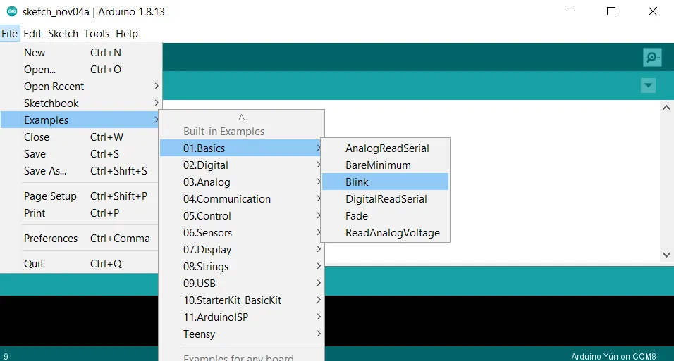
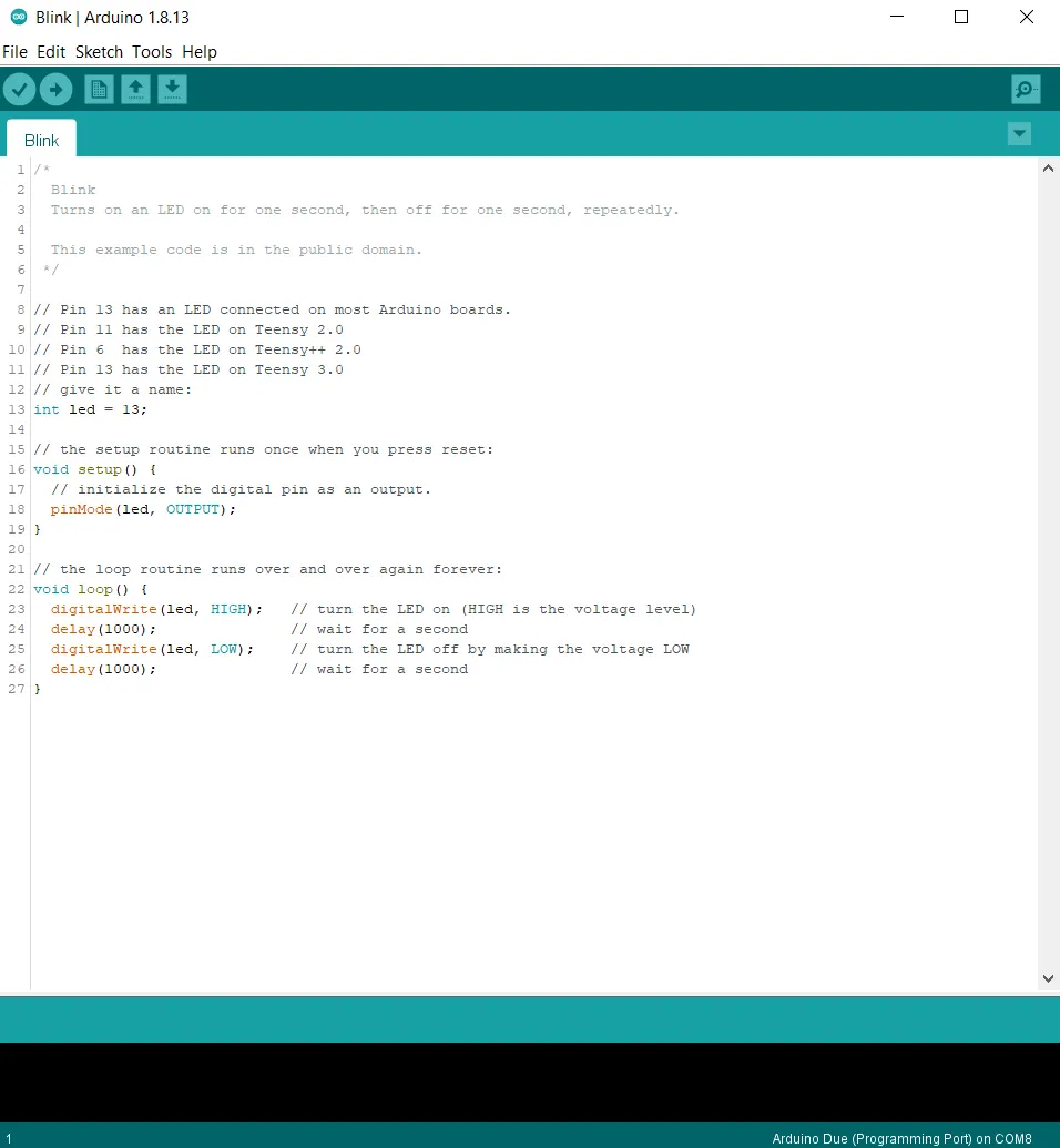
The easiest way to check if the board is working, is to use pre-created example codes. One of them is the blink sketch provided in the Arduino IDE examples.
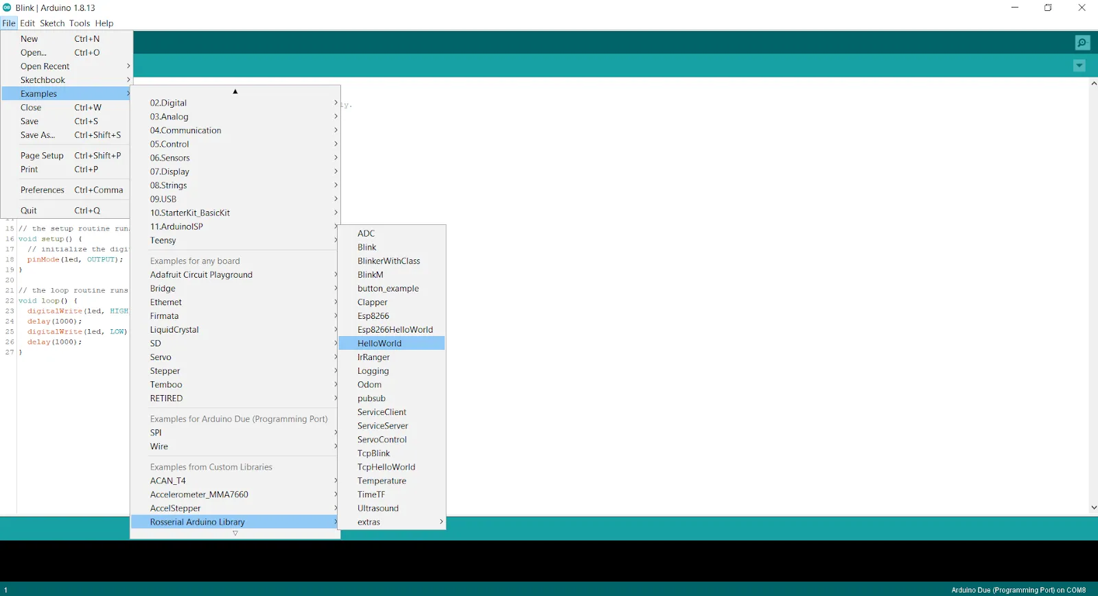
Go to: File -> Examples -> 01.Basics and choose the Blink sketch
You should see something similar to this:
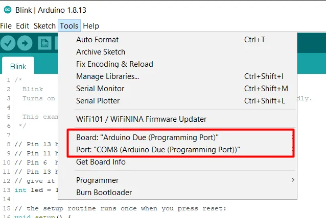
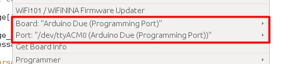
Now, you'll have to verify the code and send it to the board. First, make sure the correct board and ports are chosen as shown below:
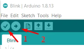
Now you can verify(1) and upload(2) the code.
After a few seconds, you should see two things:
- the following statement:
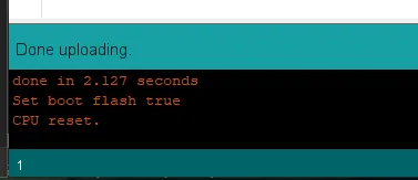
- and Arduino's built-in LED blinking
Setting up the Rosserial communication
First step is to download the rosserial library.
Go to: Tools -> Manage Libraries
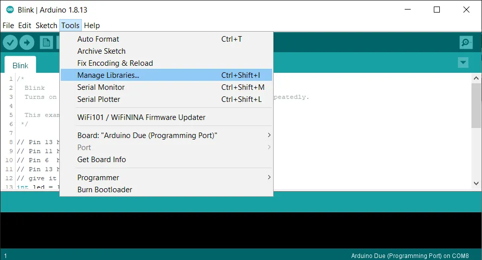
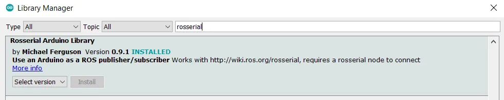
Type rosserial in the search bar and download Rosserial Arduino Library
The board that we are using - Arduino Due - needs one additional step in order
to properly work with rosserial.
Skip this step if you are using another board.
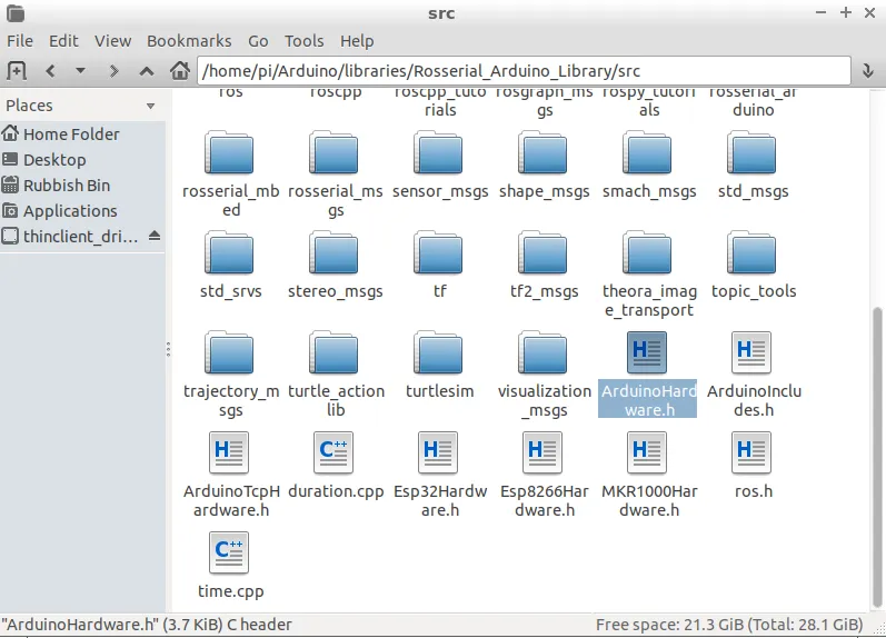
Find ArduinoHardware.h. The proper path to find the folder is as follows:
/Arduino/libraries/Rosserial_Arduino_Library/src
Modify line 73 to state:
#if defined(USBCON) and !(defined(USE_USBCON)) and !(defined(_SAM3XA_))

Examples
From this point forward, most of our instructions will be rephrased instructions
made by wiki.ros.org. You can check
this site for more detailed
instructions.
In the first tutorial, you can see how to get data from Arduino to the rover`s mind.
Arduino Code (hello world - simple publisher)
You can get to the sample code by following the path shown below:
Upload the code to Arduino. Make sure to use the correct PORT and BOARD in
Arduino.
Then, start a new terminal window and launch rosserial node, that will start
communication between Arduino and the rover's onboard computer.
rosrun rosserial_python serial_node.py port:=/dev/ttyACM0 __name:=my_node
Remember to set the port argument, to the same port you saw in Arduino IDE.
__name argument can be set to whatever you like your node to be called
Start another terminal window and check the list of running nodes (you should see your node there):
rosnode list
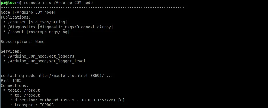
You can get more information about your node - eg. what topics it is
listening/publishing to. As you can see, /Arduino_COM_node is publishing to
/chatter topic
rosnode info /node_name
After /, you need to provide the correct name of your node. You can start
typing the name, and fill the line with Tab key (double tap).
You can also see list of all active topics by typing:
rostopic list
You should see one called chatter that was created by Arduino after you've
created the node you've named.
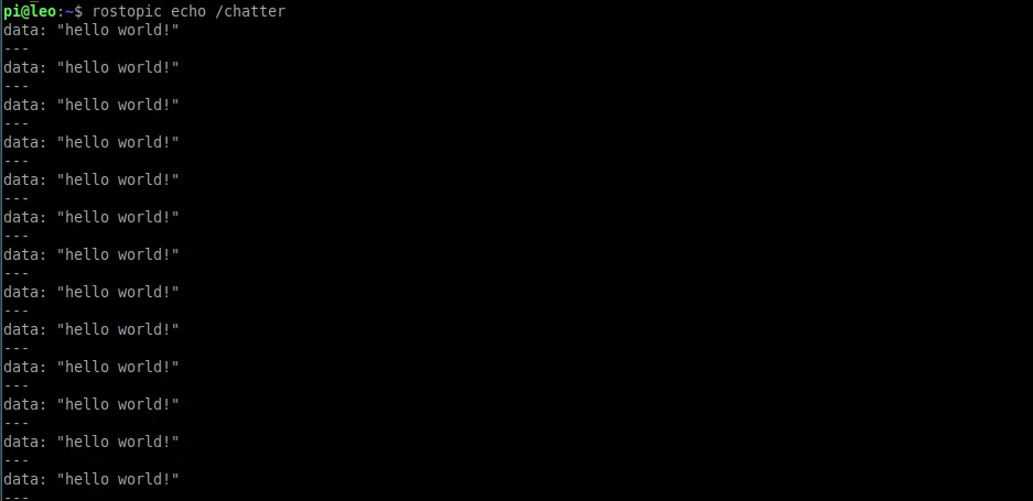
Now to see data published to our topic, type in the terminal:
rostopic echo /chatter
If everything went according to our plan, by running this command you should be able to see the Arduino sending “Hello World” message to this topic.
Ctrl+C lets you stop the program running in the terminal.
Arduino as publisher and subscriber
In this example, we will show you our real live use case of Arduino with Leo Rover.
Description
Our task was to check whether there is a correlation between soil quality and motor current in Leo Rover pulling a plow. Therefore we have designed a lowered plow, capable of gathering pulling force data and drove Leo Rover through soil of different quality, while gathering the data. And in the end, we could analyze gathered data.
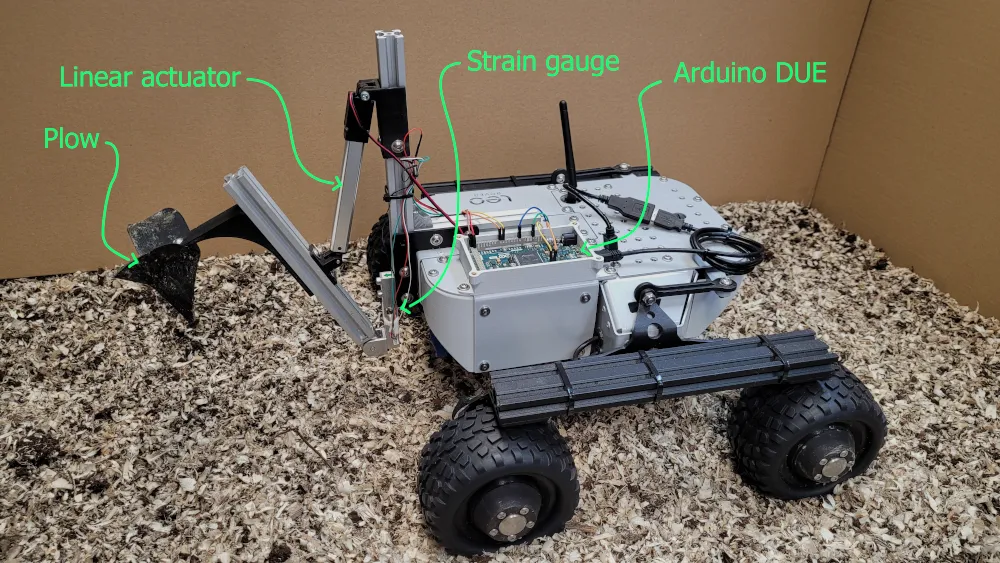
The Plow is connected to the rest of the rover with a strain gauge beam. Pulling force can be observed as tiny changes in voltage, that get amplified with an amplifier. Arduino is used to gather the data and send it to the computer.
It's obvious that you will not be able to follow this guide with a plow, so you can replace it with a potentiometer or any other analog sensor. Here are the instruction, how to connect it, so it works with the rest of the tutorial:
- Connect your sensor to
A0 pinon Arduino, - Use 2 LEDs connected to respectively digital pin 10 and digital pin 11 (remember to use resistors) to test the subscriber part of the code.
Code
#include <Arduino.h>
#include <ros.h>
#include <std_msgs/Bool.h>
#include <std_msgs/Float32.h>

ros::NodeHandle  nh;

std_msgs::Float32 tension_msg;
std_msgs::Bool plow_state;

void plow_control_callback( const std_msgs::Bool& msg){

  if(msg.data == true){         //plow up
    digitalWrite(10, HIGH);
    digitalWrite(11, LOW);
  }
  else if (msg.data == false)    //plow down
  {
    digitalWrite(10, LOW);
    digitalWrite(11, HIGH);
    }
}

//setup a publisher
ros::Publisher pub_tension("tension", &tension_msg);
//setup a subscriber, make Arduino react to a message with plow_control_callback function
ros::Subscriber<std_msgs::Bool> plow_control ("plow_control", &plow_control_callback );

void setup()
{
  //actuator pins setup
  pinMode(10, OUTPUT);
  pinMode(11, OUTPUT);

  //rosserial communication setup
  nh.initNode();
  nh.subscribe(plow_control);    //make arduino listen to messages sent to a plow_control top-ic
  nh.advertise(pub_tension);     //give arduino the ability to send messages to pub_tension topic
}
void loop()
{
  //get data and publish it
  tension_msg.data = analogRead(A0);
  pub_tension.publish(&tension_msg);
  nh.spinOnce();
  delay(1);
}
Running and visualizing
With the code imported to Arduino and all the necessary wires connected, you can start the Arduino node. To do so, open new terminal and type:
rosrun rosserial_python serial_node.py _port:=/dev/ttyACM0 __name:=Arduino_node
In another terminal run:
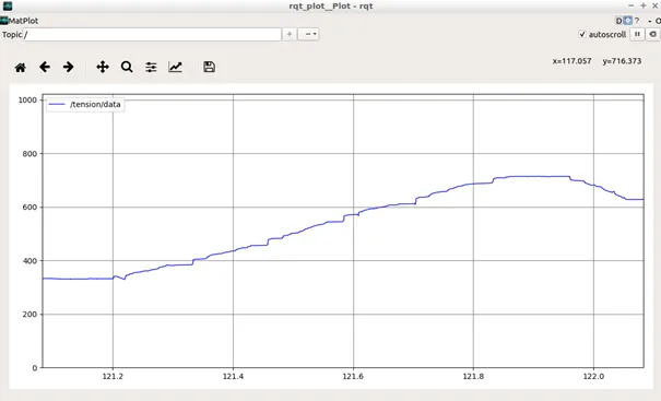
rqt_plot /tension/data
You`ll see a graph following the changes in sensor output.
Sending either True or False to plow_control topic controls the plow
position for us (either lowered or raised) for you it can control any binary
device e.g. turn the LEDs on and off. You can send those messages by typing in
the terminal:
rostopic pub /plow_control std_msgs/Bool „data: false”
or:
rostopic pub /plow_control std_msgs/Bool „data: true”
For instructions related to data recording refer to
this site. And If you want to make
recordings easier to use, you can change .bag files to .csv files by
following this tutorial.
What next?
If you want to Learn more about working with ROS (e.g. make arduino node start on Leo Rover startup) check this tutorial.
You can also find other ideas and tutorials here:
- https://create.arduino.cc/projecthub/projects/tags/arduino
- http://wiki.ros.org/rosserial_arduino/Tutorials
Now, everything should work, if not, contact us at [email protected]. We'll be happy to answer your questions and help you.