Raph Rover Specification
Key parameters
| Parameter | Value |
|---|---|
| Dimensions (LxWxH) | 559 mm x 474 mm x 255 mm |
| Weight | 12.5 kg |
| Maximum payload | 10 kg |
| Maximum linear speed | 1.8 m/s |
| Maximum angular speed | 4.7 Rad/s |
| IP protection rating | IP 54 |
| Operating temperature | -10 °C to +40 °C |
| Run time | 4 hours* |
| Connection range | Up to 100 m |
* - infinite with hot swapping batteries
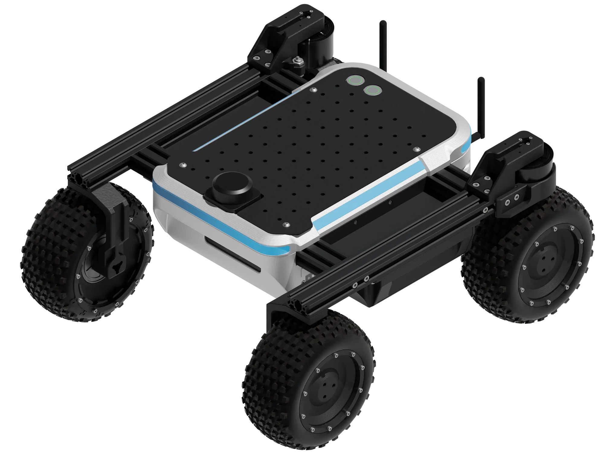
Rover overview


Hardware
Dimensions
| Parameter | Value |
|---|---|
| Length x Width x Height | 559 mm x 474 mm x 255 mm |
| Weight | 12.5 kg |
| Track Width | 385 mm |
| Wheelbase length | 382 mm |
| Ground clearance | 80 mm |
| Wheel diameter | 170 mm |

Speed and performance
| Parameter | Value |
|---|---|
| Maximum linear speed | 1.8 m/s |
| Maximum angular speed | 4.7 Rad/s |
| Climb grade (no payload) | 30° ( ~58%) |
| Climb grade with 5kg payload | 20° ( ~36%) |
| Climb grade with 10kg payload | 10° ( ~18%) |
| Hill grade traversal | 30° ( ~58%) |
| Nominal torque | 4 Nm |
| Maximum torque | 8 Nm |
Drivetrain
Raph rover is equipped with two independent steering wheels on the rear of the robot. It enables great agility of the robot as well as precise manoeuvres such as:
- Following a curve
- Rotate around middle
- Rotate around front wheel


Wheels
As standard, Raph Rover comes with rubber tires with a diameter of about 170 mm. Whole drive assembly has following characteristics:
| Parameter | Value |
|---|---|
| Tire size (diameter x width) | ~ 170 mm x ~ 80 mm |
| Tire lock type | Beadlock |
| Tire insert | Hard foam |
| Wheel rim diameter | 120 mm |
Components
| Name | Quantity | Description |
|---|---|---|
| Built-in computer | 1 | UPBoard 7000 - Credit card-sized SBC based on the Intel N100 CPU - CPU: Intel® N100 quad-core (x86 architecture) - Memory: 8GB LPDDR5 - Storage: 64GB eMMC - Connectivity: - 1 Gigabit LAN - HDMI 1.4b - 3 USB 3.2 Gen 2x1 (10 Gb/s) - 2 USB 2.0/UART - 40-pin GPIO header Full specification |
| Router | 1 | Teltonika RUTX10 - Industrial router with with Gigabit Ethernet, Bluetooth LE, and AC Wi-Fi. - WAN: 1 x 10/100/1000 Mbps - LAN: 3 x 10/100/1000 Mbps - Wi-Fi: 802.11b/g/n/ac Wave 2 (Wi-Fi 5) - Bluetooth: 4.0 Full specification |
| Controller | 1 | RaphCore - Custom Fictionlab's controller designed for Raph Rover. See more |
| Antenna | 2 | Dual-band (2.4 GHz / 5 GHz) placed on the rear of the robot. |
| Stereoscopic camera | 1 | Luxonis OAK-D Pro W IMX378 - a wide-angle camera with active stereo depth and high-resolution color capabilities. - RGB sensor: IMS 378 - RGB sensor resolution: 12 MP - RGB sensor DFOV: 120° - Stereo sensors: OV9282 - Stereo sensor resolution: 1 MP - Stereo sensor DFOV: 150° Full specification |
| Lidar | 1 | RPLidar S3 - 360-degree waterproof 2D Lidar scanner with a 40-meter range. - Coverage: 360° - Max range: 40 m - Sample rate: 32 kHz (32 000 points per second) - Angular resolution: 0.1125° Full specification |
| Battery | 2 | 6S (22.2V) 4 Ah Li-ion battery - Custom battery pack with hot-swappable connectors. See more |
| BLDC motors | 6 | BLDC motors with integrated controllers. Connected to RaphCore board via RS 485 bus. See more |
| LED strip | 4 | 143 RGBW Individually addressable LEDs. Used as rover status indicator as well as any custom purpose programmed by the user. - Form factor: 3535 - Density: 144 LEDs/m - Power: 23 W - Temperature: 6000-6500K. - Luminance R: 46; G: 156; B: 34; W:409 lm |
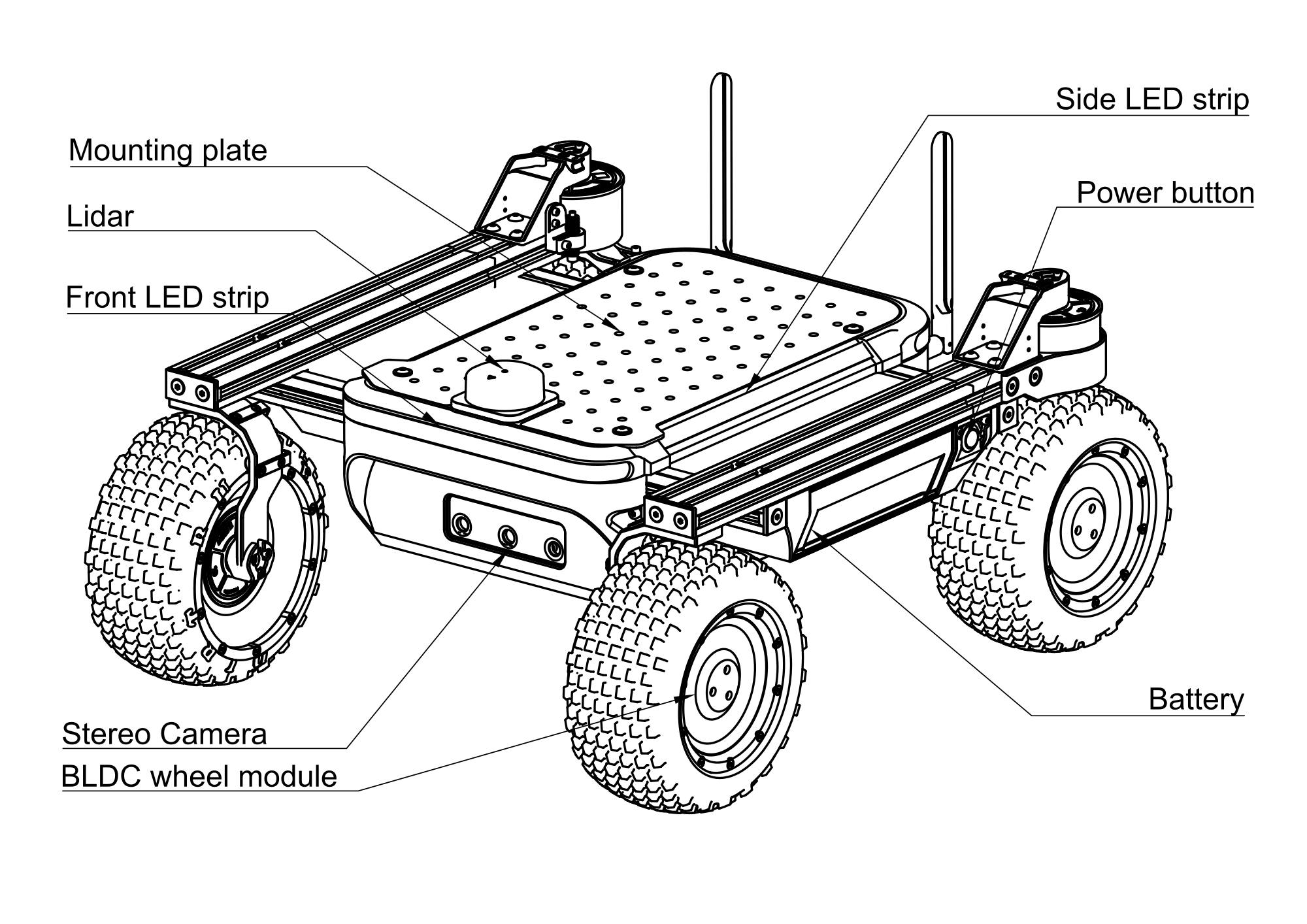
Component's diagram

Battery
Raph rover's batteries are enclosed in specially designed case, allowing them to be quick swappable. Each pack has its own BMS that manages charging, discharging and has built-in protections.
| Parameter | Value |
|---|---|
| Battery type | Li-Ion |
| Battery pack type | 6S1P |
| Nominal voltage | 21.6 V |
| Charge capacity | 4 Ah |
| Energy capacity | 86.4 Wh |
| Maximum output power | 650 W |
| Battery cell | Samsung INR21700-40T |
| Safety systems | Overcurrent, Undervoltage, Reverse polarity, Overheat |
RaphCore controller
RaphCore serves as the primary control board for Raph Rover. The board leverages FreeRTOS and MicroROS to control rover tasks such as:
- Drivetrain control
- Power system management
- LED control
- IMU operation
- Odometry tracking
Operating conditions
- Operating temperature range: -20°C - +50°C
- Nominal battery voltage: 24 V (Li-Ion 6S)
- External power input: 12 - 27 V DC
- Environmental protection: Over-voltage and reverse-polarity protection, PTC and TVS fuses on all major power lines

Power & Connectivity
RaphCore integrates automatic source switching, current limiting and voltage
conversion between battery and external supply modes.
The design enables safe charging, load balancing, and protection against surges
or incorrect polarity.
| Connector | Description |
|---|---|
| Ethernet port | Standard RJ45 connector with onboard PHY for wired communication and networking. |
| Router power | 12 V / 1 A regulated output dedicated to powering an external Wi-Fi router. |
| Main computer power (UP Board) | 12 V / 5 A output supplying the onboard computer. |
| External power / charging port | Input for 12 - 27 V DC external power or battery charging. Includes reverse-polarity and surge protection, max 5 A. |
| 5 V output (2-pin) | 5 V / 4 A max (20 W) auxiliary power line for external devices mounted inside. Connector: Phoenix Contact MC 1,5 / 2-ST-3,5 |
| 12 V output (2-pin) | 12 V / 4 A max (48 W) auxiliary power line for external devices mounted inside. Connector: Phoenix Contact MC 1,5 / 2-ST-3,5 |
| BAT output (2-pin) | 18 - 25.2 V / 4 A max (100 W) direct battery line for high-power accessories mounted inside. Connector: Phoenix Contact MC 1,5 / 2-ST-3,5 |
| 5 V / 12 V / BAT power bus (6-pin) | Combined 6-pin connector providing 5 V, 12 V and BAT lines (the same as above). See more Connector: Phoenix Contact MC 1,5 / 6-ST-3,5 |
| Battery A / Battery B inputs | Dual Li-Ion 6S (24 V nominal) inputs with 30 A fuses and over-voltage protection. |
Control & Sensors
| Component | Description |
|---|---|
| 8 x motor power connectors | Two motor sections (4 connectors each), up to 8 A combined per section. |
| 4 x inductive sensor inputs | Inputs for wheel encoders or proximity sensors. |
| LED strip output | 5 V / 5 A output with PWM control channel for addressable LED strips. |
| Power button / Emergency stop / Calibration button | Dedicated safety and control inputs for rover operation. |
| Programming port | SWD + UART interface for firmware upload and diagnostics. |
| IMU module | TDK ICM-42605 - 6-axis accelerometer and gyroscope. Acceleration: ±2 g / ±4 g / ±8 g / ±16 g Resolution: 16 bit Sensitivity: 2097.2 deg/s/LSB |
| Microcontroller | STM32H563VIT6 (Arm® Cortex®-M33, 250 MHz, 2 MB Flash, 640 kB RAM). |
Payload
The Raph Rover is engineered for easy and versatile payload integration. If your sensor or hardware is ROS 2-compatible and falls within the rover's power (5V 4A, 12V 4A, and 24V 4A) and weight limits (10 kg), you can be confident in its compatibility.
External data ports

| Interface | Notes | Device connected |
|---|---|---|
| USB type A | USB 3.2 Gen 1 (5 Gb/s) | UPBoard 7000 (Main computer) |
| USB type C | USB 3.2 Gen 1 (5 Gb/s) | UPBoard 7000 (Main computer) |
| HDMI | HDMI 1.4b | UPBoard 7000 (Main computer) |
| RJ-45 | 10/100/1000 Mb/s | Teltonika RUTX10 (Router) |
External power panel
| Voltage | Max amperage | Max power | Connector |
|---|---|---|---|
| 2 x 5 V | 4 A | 20 W | Phoenix Contact MC 1,5/ 2-ST-3,5 |
| 2 x 12 V | 4 A | 48 W | Phoenix Contact MC 1,5/ 2-ST-5,08 |
| 2 x BAT (18-25.2 V) | 4 A | 100 W | Phoenix Contact MSTB 2,5/ 2-ST-5,08 |
Total amperage and power is shared between 2 connectors on the external panel, so for example it is possible to connect 1 device that uses 4 A or 2 devices that use 2 A each.
Mechanical connections

| Parameter | Value |
|---|---|
| Payload capacity | 10 kg |
| Hole grid spacing | 25 mm x 25 mm |
| Mounting hole dimensions | 5.4 mm, compatible with: M5 screws CLS-M4-1 press-in nuts |
| Mounting plate dimensions (L x W x D) | 330 mm x 198 mm x 2 mm |
Apart from the mounting plate, it is possible to mount payloads directly to v-slot extrusions of the Raph Rover, effectively providing a 360 mm by 430 mm working area.
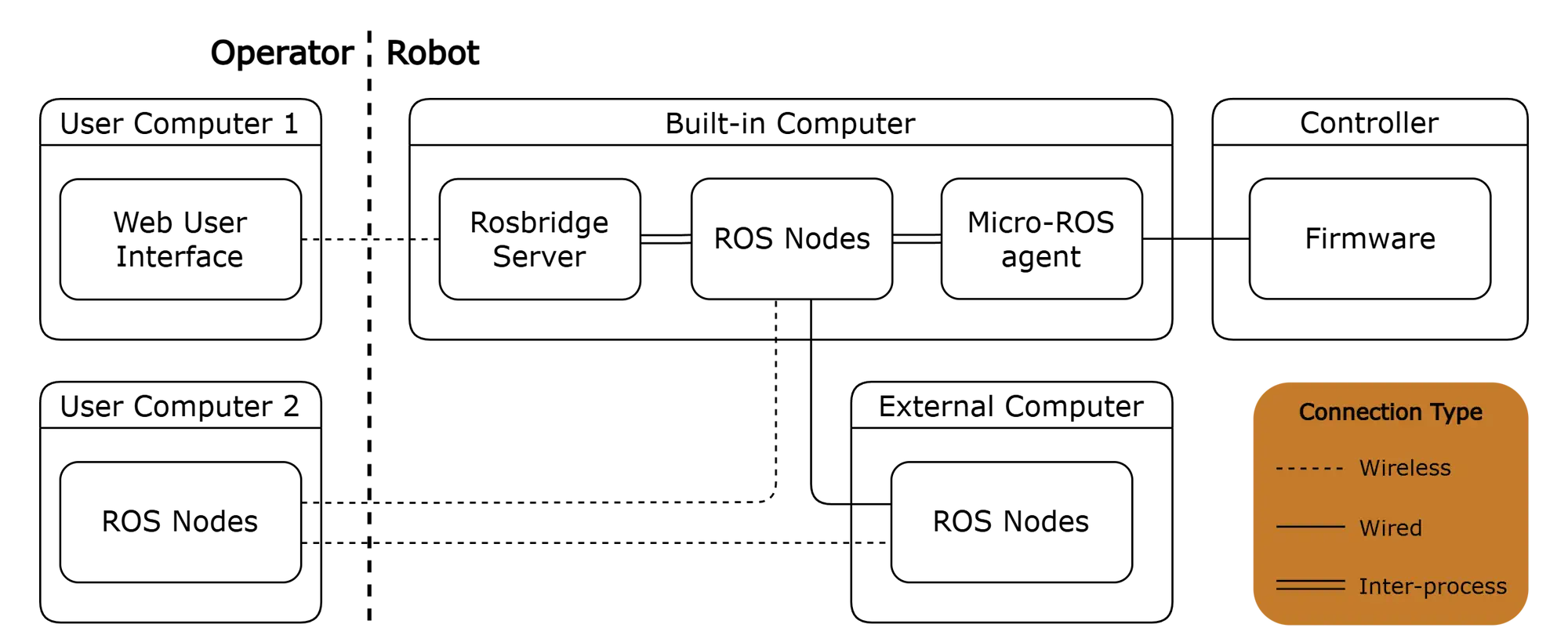
Software & Control
| Parameter | Value |
|---|---|
| Operating System | Ubuntu 24.04 LTS |
| Core Framework | ROS 2 Jazzy |
| User Interface | Web-based GUI accessible over Wi-Fi |
| UI Features | Real-time teleoperation, live video streaming, system monitoring |
| API Access | Full control via standard ROS 2 topics, services, and actions |
| Software license | MIT License |
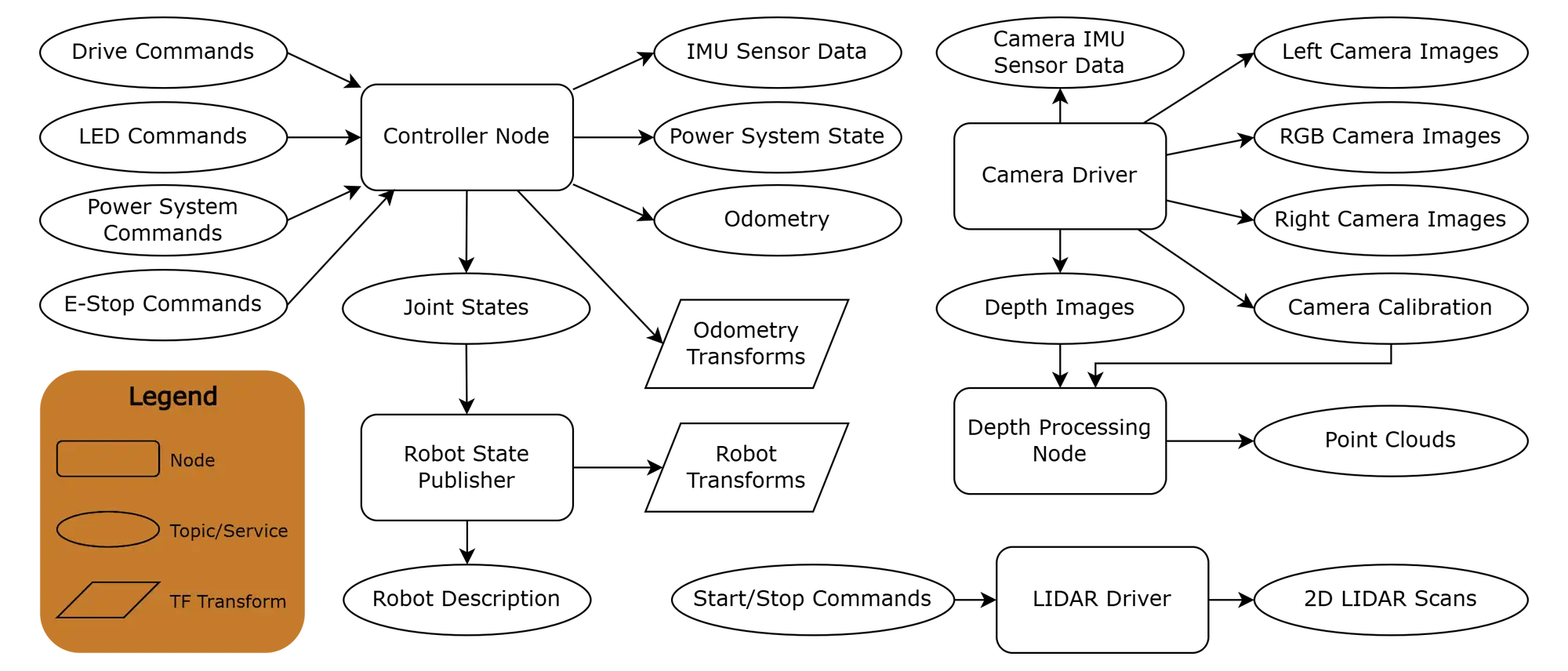
ROS nodes